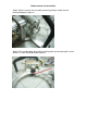
Blade removal and installation Step 1: Remove blade guard and splash flap using 9/16” wrench provided (figure 1). Figure 1 Step 2: Remove adjustable arm assembly (figure 2).
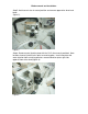
Blade removal and installation Step 3: Relieve transmission assembly tension by pulling t-handle out and turning 90 degrees (figure 3) Figure 3 Step 4: Disassemble upper drive roller by locking roller and removing allen screw with the ¼” allen wrench provided (figure 4).
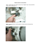
Blade removal and installation Step 5: Hold transmission in neutral position and remove upper drive wheel and blade (figure 5). Figure 5 Step 6: Remove water injection plate with the 5/32” allen wrench provided. Note location of water injection holes prior to removing plate. Install new plate with water injection holes matching previous mounted location (outer right side opposite from drive wheel)(figure 6).
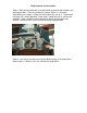
Blade removal and installation Step 7: Inspect lower drive roller for wear on lip. Replace if lip is worn to half the original width (.200”)(figure 7). Figure 7 Step 8: Install new blade, matching groove in blade to lip on the lower drive roller.
Blade removal and installation Step 9: With the transmission assembly in neutral position, reinstall upper drive roller using the ¼” allen wrench provided. Tighten securely by locking drive wheel in position (figure 9). Figure 9 Step 10: Using 5/32” allen wrench provided, remove guide roller cover and inspect both guide rollers for wear or damage. Guide rollers should spin freely. Replace if necessary (figure 10).
Blade removal and installation Step 11: Reinstall adjustable arm assembly, blade guard and splash flap on saw. Hand tighten bolts. Place ring saw on flat surface (figure 11) so that the adjustable arm assembly is sitting with the weight of the saw on it. Tighten bolts using the 9/16” wrench provided. Guide rollers should be firmly in contact with the blade. Move t-handle to original location by pulling up and rotating 90 degrees, returning transmission assembly to the tensioned position.