ULTIMATE DRILLING MACHINE OPERATING SUMMARY STARTING: The function switch at the rear control panel must be in the center (Neutral) position between DRIVE & DRILL, and the MASTER DISCONNECT switch must be ON. Be certain both red EMERGENCY STOP switches are pulled out. The engine throttle, choke and start key are all located at the rear of the machine on the right side of the engine. MOVING: The self propelled function only works with the function switch in the DRIVE position.
Table of Contents Safety Precautions Safety Alerts Proposition 65 Spark Arrester Requirements Repertory Hazards General Safety Battery & Electrical Safety Drill Safety Fuel Safety Engine Safety Hydraulic Safety Belt Safety Transportation Safety Lifting Safety Introduction to The UDM Components Controls Dimensions & Specifications Operating The UDM Light Tower Lift Points Fuel System Battery Engine Drive Lever Water System Vacuum System Drill Mode Diamond Core Bits Stuck Cores Stuck Bits Maintaining UDM Mai
Safety Precautions Operate the Ultimate Drilling Machine (UDM) and all of its components according to this manual. Failure to comply with and understand the following safety, operations, and maintenance instructions can result in serious injuries and/or death. All operators must be properly trained or supervised by experienced personnel prior to using the machine and should understand the risks and hazards involved.
General Safety • • • • • • • • • • • • • • Read and understand all safety, operations, and maintenance instructions provided in this manual prior to operating or servicing the machine. Keep the machine clean and free of slurry, concrete dust, and debris. Inspect water hoses prior to operating the machine. Clean, repair, or replace damaged components. Repair the machine immediately if a problem arises. Replace machine decals if unreadable.
Drill Safety Inspect all core bits prior to usage and discard damaged bits. Remove debris from bits and clean as necessary. Keep all body parts away from rotating core bits. Always use an appropriate size bit for the drilling task. The bit must fit tightly on the spindle shaft. Wear gloves and be alert to the surrounding environment when handling core bits. Always use the correct bit type for the material being drilled. Always start the engine with the function switch at Start/Drive.
Hydraulic Safety • • • • • • Turn off the engine prior to servicing the hydraulic system. Turn off the engine prior to disconnecting hydraulic hoses. Pay attention to the hydraulic oil thermometer. The maximum recommended oil temperature is 180°F. Remove the core bit to reduce residual pressure in the cylinder circuit prior to servicing the machine. DO NOT use external hydraulic equipment that requires a higher flow rate than what the machine is rated for.
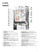
Introducing the UDM Components The UDM is a self-contained, self-propelled drilling machine with electric and hydraulic power outlets. 1. 2. 3. 4. 5. 6. 7. 8. 9. 10. 11. 12. 13. 5 Handlebar Handlebar Lock Pin/Knob Water Tank Front Control Panel Light Tower Heat Exchanger Frame Alternator Vacuum Base Mast Hydraulic Oil Tank Main Hydraulic Manifold Spindle Shaft 14. Pillow Block 15. Hydraulic Cylinder 16. Rear Control Panel and DC Fuses 17. Engine 18. Front Tires 19. Rear Tires 20. Drive Lever 21.
Controls Side Control Panel 1. Strobe Light – Powers strobe light. 2. Power Indicator - Indicates power supply to machine. 3. Vacuum Switch – Turns vacuum pump ON/OFF. 4. Rear Stabilizer Switch – Raises and lowers rear stabilizer. 5. Vacuum Lift Switch – Raises and lowers vacuum base. 6. Digital Readout – Indicates Bit RPM. 7. Auto Drill Switch – Locks the drill down function until cylinder reaches maximum length, or until switch is turned off.
Controls Rear Dash Controls 1. Mastery Battery Disconnect – Connects or disconnects battery circuit. NOTE: Always disconnect when finished operating machine. 2. Function Switch – Three position switch. Up position is Drill mode, center is Start/Neutral Mode, and down position is Drive Mode. 3. Emergency Stop Button – Stops engine and all systems of machine.
31.00” 73.25” 81.75” Ultimate Drilling Machine Specifications Overall Height Overall Width Overall Length Overall Length W/ Handlebars Extended Weight (Add 450lbs.
Light Tower Use the strobe light to alert others when operating the machine. Use the spotlight for additional lighting as necessary. Fuel System DO NOT operate the machine with a fuel leak. DO NOT fuel the machine with the engine running. DO NOT smoke or expose fuel to open flames when filling the fuel tank or working with fuel. Clean up spilled fuel prior to starting the engine. Fueling the Machine 1. Turn off the engine and let the machine cool down. 2. Remove the fuel tank cap. 3.
1. Turn on the master battery disconnect to connect the circuit (the indicator light directly below will light up when activated). Note: The strobe light, spotlight, water pump, and rear and front raise/lower cylinders will operate with the engine off and master battery disconnect on. Be careful not to drain the battery when using these items with the engine off and battery connected. 2. Turn off the master battery disconnect to disconnect the circuit. Engine • DO NOT leave the engine running unattended.
Water System Use extreme caution when operating the machine on slopes, as it is more susceptible to sideways tipping/rolling over, especially with a full water tank. The water system cools the core bit and flushes slurry from the drilling hole. Note: Always test the water supply for adequate pressure and flow prior to drilling. Filling the Water Tank NOTE: Too much water makes the slurry look clear and waste water, insufficient water makes slurry thick and can result in a core sticking in bit.
Water Jars The primary jar is mounted on the water tank next to the side dash unit and helps keep water and other contaminates from being sucked into the pump. The secondary jar is located adjacent to the vacuum pump behind the form right wheel of the machine. Visually inspect and empty the containment jar on a regular basis. The jars unscrews by hand. Failure to empty this jar will result in vacuum pump damage.
Drill Motor Pressure Switch An adjustable pressure switch monitors the drill motor pressure and will automatically shift the cylinder to neutral (stops pushing) if it senses the drill motor pressure rises above 1500 psi (hard spots). The cylinder will then automatically cycle ON/OFF as the drill works through rebar or other hard spots. • • DO NOT exceed the core bit’s maximum recommended speed when drilling.
• Wear gloves and be alert to the surrounding environment when handling core bits. 1. Select the correct core bit size and type for the drilling task. 2. Raise the spindle shaft to provide room to install the core bit. 3. For smaller core bits: Holding the bit with both hands, screw the hub onto the spindle shaft until it bottoms out on the shaft. Make sure the bit is secure (the bit will tighten further once it enters the concrete). 4.
Drilling a Hole Reminder: Always refer to the Drill Mode section in Operating the U to set the cylinder pressure and drill motor pressure prior to drilling. 1. Position the machine and core bit. 2. Move the function switch to Drill. 3. Lower the front mast and rear legs. All tires should just clear the ground and the front and rear tire height should match up so the machine is level. 4. Turn on the Vacuum switch and close the vacuum valve.
Removing a Stuck Bit 1. Release the Drill Down button or turn off the Auto Drill switch. Press the Drill Up or Drill Down button and Turbo button together to raise and lower the bit to try and free it. Note: If the bit is not spinning, turn the Drill Rpm cartridge on and off to try and get the bit to spin (this will cause the drill motor pressure to max out). If the bit is spinning, try to keep it spinning while attempting to raise the bit. Continue with step 2 if this attempt fails. 2.
Maintaining the UDM Failure to read and comply with the maintenance instructions provided in this manual prior to performing maintenance may result in serious injuries and/or death, and may harm the machine. DO NOT attempt to perform maintenance on the machine if you are not properly trained for it, or are not supervised by an experienced person. Refer to the Diamond Products’ Parts List for additional information and part diagrams when performing maintenance tasks.
Battery Ignitable explosive gases are emitted from the battery. DO NOT expose the battery to sparks or open flames, and keep the area around the battery well-ventilated. • Always keep the battery cable clamps away from the battery terminals when the battery is disconnected to avoid accidental connections. Disconnect the battery prior to servicing the machine unless stated otherwise. 7. • • • Use a proper battery tester when testing the battery strength.
Hydraulic System • • Always use a piece of cardboard or paper to check for hydraulic fluid leaks. Keep all body parts away from leaks and/or areas that may eject hydraulic fluid. Pressurized hydraulic fluid can penetrate the skin, causing serious injuries. Seek medical attention immediately! Remove the core bit to reduce residual pressure in the cylinder circuit prior to servicing the machine. 2. Unscrew the filter and hold it over the tray to catch falling oil.
3. Turn the belt adjustment shaft nut clockwise to tighten the belt. Retest the tension and readjust the nut as necessary to reach the required tension setting. DO NOT exceed the manufacturer’s setting. 15. Slide the alternator toward the side of the machine (this will tension the belt slightly). 16. Turn the belt adjustment shaft nut clockwise to tighten the belt. Test the tension and readjust the nut as necessary to reach the required tension setting. DO NOT exceed the manufacturer’s setting. 17.
Appendix A Serial Tags Record the machine’s serial number below for future reference and customer service purposes. Serial Number Record the engine’s model and serial numbers below for future reference and customer service purposes. Model Number Serial Number Appendix B Daily Maintenance Task Chart Table 1: Daily Maintenance Task Chart Date 1. Inspect belts for tension and wear. Replace or re-tension as necessary. 2. Inspect machine for damages. 3. Tighten loose nuts, screws, and bolts. 4. 5. 6.
Appendix C Belt Tension Setting Table 1: Belt Tension Setting Model Engine Type Deflection Deflection Force Ultimate Drilling Machine (UDM) 20.5HP Honda GX670 to 5000 W Alternator .10” 69 lb Deflection (in.) should be equal to number of inches listed in chart above when deflection force (lb.) listed in chart above is applied to middle of belt using tension gauge. Appendix D Additional Resources 1. Diamond Products (www.diamondproducts.
Appendix E Troubleshooting Table 1: Troubleshooting Symptom 1. Core bit will not raise/lower. 2. Machine will not move forward/backward. 3. Controls/buttons/switches do not work. 4. Hydraulic outlets do not work. 5. Electrical outlets do not work. Problem Engine off? Function switch in Drill mode? Engine off? Start engine. Move function switch to Drill. Start engine. Function switch in Drill mode? Move function switch to Start/Drive.
ULTIMATE DRILLING MACHINE OVERVIEW 1 2 3 10 4 9 5 6 7 8 ITEM NUMBER 1 2 3 4 5 6 7 8 9 10 PART NUMBER 6079001 6079058 4645238 6079205 4645207 6079184 6079000 2400276 4645216 6079002 DESCRIPTION Fuel Tank Weldment Dash Assembly Drill Mast Assembly Rear Stabalizer Assembly RIght Body Panel Hole Guide Hydraulic Tank Weldment 16.00" x 4.
29 30 31 1 2 38 3 27 4 26 5 25 6 7 9 10 11 UDM DRIVETRAIN ASSEMBLY 8 34 35 35 36 37 12 13 14 32 22 22 33 24 16 17 18 19 20 21 22 23 15 25
ITEM NUMBER 1 2 3 4 5 6 7 8 9 10 11 12 13 14 15 16 17 18 19 20 21 22 23 24 25 26 27 28 29 30 31 32 33 34 35 36 37 38 ULTIMATE DRILLING MACHINE DRIVE TRAIN ASSEMBLY PART NUMBER 4645109 4640108 4645159 4645039 6079178 2400276 2900279 2500001 4645199 2500584 4646122 6079179 2600569 4645129 4600158 2503909 2702624 6091138 2500201 6079181 2900013 2900473 2900033 6079001 6079182 2505503 2503294 2804510 2800122 2801367 2701670 2900047 2900018 2901405 2900126 2900024 2900125 2400294 DESCRIPTION Ultimate Drilling
4645159: AXLE ASSEMBLY NOTE BEARING ORIENTATION 6 5 8 9 7 3 6 3 3 5 5 4 2 1 4 5 ITEM NO. 27 PART NUMBER DESCRIPTION QTY. 1 2 4645114 2400298 Axle Shaft Bearing, 1-1/4 x 1-1/2 x 1.0" 1 1 3 2400299 Key, 1/4 x 1-3/4" 3 4 2500365 Pillow Block Bearing, 1-1/4" 2 5 2500009 Set Collar, 1" ID 4 6 7 2400277 2900057 Tire, 12 x 3-1/2, Foam Filled 3/8-16 x 3.
4645039: ALTERNATOR ASSEMBLY, 5KW 5 4 3 1 7 8 7 4 PLACES 7 6 9 9 ITEM PART NO. QTY. DESCRIPTION 1 3 4 5 6 7 8 9 2800851 2501538 2400283 2400281 4600100 2900047 2900013 2900018 1 1 1 1 1 9 4 5 Alternator, 5000 W., 115/230 V., 42/21 Amp Square Key, 1/4 X 1-3/8" Bushing, QD, 1-1/8" Pulley, 3.11 OD x 1-1/2" Belt x1/2" Pitch Belt Adjustment Assy. 3/8 Flat Washer Cap Screw, Hex Hd.
29
ULTIMATE DRILLING MACHINE WATER & VACUUM SYSTEMS ITEM NUMBER 1 2 3 4 5 6 7 8 9 10 11 12 13 14 15 16 17 18 19 20 21 22 23 24 25 26 27 28 29 30 31 32 33 34 35 36 37 38 39 40 41 42 PART NUMBER 6079002 3200136 3200727 3205539 3205892 3205767 3205891 3201349 6079170 3205904 3205766 6079169 2900196 2900006 6079168 3200390 3205536 3201330 3201525 4646213 3201516 3205903 6079171 6079172 2701694 2600545 2900126 2503269 2900125 4645157 3201366 3205537 3205583 6079173 6079174 6079175 6079176 3201271 3205535 6079177
VACUUM PUMP ASSEMBLY 4 3 2 5 6.1 1 4 6.3 TO VACUUM GAGE AND VALVE AT FRONT PANEL. 6.4 6.2 8 A 6.5 9 6.6 DETAIL A SCALE 1 : 4 ITEM NO. PART NUMBER 31 10 QTY. DESCRIPTION 1 2 4645143 3200007 1 1 Vacuum Pump Assy., 115V, W/ Connectors Close Nipple, 1/4 NPT 3 3200010 1 Pipe Tee, 1/4" FPT 4 3200012 2 Street Elbow, 1/4" NPT 5 3200088 1 Nipple, 1/4 MPT x 2-1/2", Sched. 40, Galv. 6 2700171 1 Water Jar Assembly 6.1 2700014 1 Water Jar Lid 6.
4645134 OUTLET BOX 1 8 10 8 11 10 11 39 9 19 38 37 16 15 16 3 4 5 7 7 7 6 12 13 18 17 18 14 17 32
ULTIMATE DRILLING MACHINE ELECTRICAL OUTLET BOX ITEM NUMBER 1 3 4 5 7 8 9 10 11 12 13 14 15 16 17 18 19 37 38 39 33 PART NUMBER 4645127 4648047 2800858 2800859 2900017 2900009 2900416 2900024 2900125 2800089 2800430 2800698 2800801 2800791 2800171 2801304 4645135 1800810 1801348 1800415 DESCRIPTION Electrical Box Front Mount Bracket 20 AMP Circuit Breaker 40 AMP Circuit Breaker #10-24 Lock Nut ¼” SAE Flat Washer ¼”-20 x ½” Hex Head Tap Screw 1 ¼” Split Lock Washer ¼-20 Hex Nut 20A 250V Twist lock Recepta
DASH PANEL ASSEMBLY 31 23 30 29 28 26 32 8 9 11 27 20 14 16 21 ITEM NO.
UDM INNER DASH CONTROL PANEL 13 A 21 14 20 19 17 16 A 18 15 SECTION A-A SCALE 1 : 3 ITEM NO. 13 14 15 16 17 18 19 20 21 35 PART NUMBER 2800872 2800144 2808037 2800635 2801328 2800291 2800512 2800560 91773A194 DESCRIPTION Relay, 75 Amp, 12 V, SPST Relay, 50 Amp, 12V, SPDT 12 Fuse BLock Fuse, 5 Amp, Tan ATO, Blade Type) Fuse, 30 Amp Green ATO/ATC Fuse, 20 Amp Yellow ATO/ATC Fuse, 15 Amp Blue ATO/ATC Fuse, 25 Amp, Natural ATO, Blade Type) 8-32 x.750" Pan Head Screw QTY.
REAR STABALIZER ASSEMBLY 8 6 16 2 17 1 18 13 11 12 7 14 19 10 9 3 15 4 5 ITEM NO. 1 2 3 4 5 6 7 8 9 10 11 12 13 14 15 16 17 18 19 PART NUMBER 6079205 6091129 4645203 2900112 2400301 2400295 2900607 2900829 4646214 2900289 2902998 2900022 2900031 2900141 2900025 2900084 2900058 6079099 6079206 DESCRIPTION REAR COUNTER WEIGHT Tab, Rear Lift Plate Leg Hex Nut, 5/8-11 Leveling Pad, 5/8-11 Actuator, Electric, 12V, 5" Stroke Clevis Pin, 1/2" x 2-3/4" Hairpin Cotter, 1/8" x 5/8" to 7/8" 1.
8 UDM VACUUM BASE ASSEMBLY 6 4 2 9 14 15 1 7 5 3 12 11 13 10 37 ITEM NO. 1 2 3 4 5 6 7 8 9 10 11 12 13 14 15 PART NUMBER 3100014 6091074 6091075 6011468 4643027 2400295 2900607 2900058 2900029 2901111 2900033 2903087 2900084 2900829 3200669 DESCRIPTION Vaccuum Base Casting Cylinder Mount Bar Vacuum Base Mount Plate 1.00" Guide Pin VACCUM BASE GASKET Actuator, Electric, 12V, 5" Stroke Clevis Pin, 1/2" x 2-3/4" 1/2 FLAT WASHER 3/8-16 x 1.
UDM MAST ASSEMBLY 1 2 3 4 5 7 31 6 30 33 8 29 9 28 10 8 11 27 26 39 34 25 35 36 12 13 24 37 23 38 22 21 20 19 18 17 16 15 14
ULTIMATE DRILLING MACHINE DRILLING MAST ASSEMBLY ITEM NUMBER 1 2 3 4 5 6 7 8 9 10 11 12 13 14 15 16 17 18 19 20 21 22 23 24 25 26 27 28 29 30 31 32 33 34 35 36 37 38 39 39 PART NUMBER 4645109 2903140 2900042 2900362 6011472 2900829 4900159 2900062 2900037 6011467 6091072 2900693 3205754 2802597 2802596 6079096 4645141 6011484 4645238 3205536 4645215 4641167 2500009 3201525 3201516 3201366 3205537 3205583 2903114 2900113 2900202 2900811 2900084 6011483 3200968 2900837 2903094 6079168 6011470 DESCRIPTION U
51 52 53 54 55 56 57 58 59 60 61 50 1 48 47 46 49 65 2 63 45 64 66 44 3 67 43 4 42 5 6 41 7 8 40 9 12 11 39 70 10 38 14 37 13 UDM HYDRAULIC SYSTEM 36 19 62 15 34 18 17 35 20 16 A 33 69 21 25 68 71 32 5 31 30 29 28 27 26 24 23 22 DETAIL A SCALE 1 : 16
ULTIMATE DRILLING MACHINE HYDRAULIC SYSTEM PARTS LIST 41 ITEM NUMBER 1 2 3 4 5 6 7 8 9 10 11 12 13 14 15 16 17 18 19 20 21 22 23 24 25 26 27 28 29 30 31 32 33 34 35 36 37 38 39 40 41 42 43 44 45 46 47 48 49 50 51 52 53 PART NUMBER 3205754 3200726 2507002 2900037 3200286 3205894 3205761 2502924 3205765 3205893 3205876 3200785 2402418 6079165 3200967 3205657 2800641 3200739 6079152 3200111 2400296 3205895 3205864 3205657 2800697 6079166 6079167 6079153 6079158 3200505 3205578 6079159 3200626 2600561 240029
ULTIMATE DRILLING MACHINE HYDRAULIC SYSTEM PARTS LIST CONTINUED 54 55 56 57 58 59 60 61 62 63 64 65 66 67 68 69 70 71 6011483 4645238 3200105 3200104 2900693 6079162 6011470 2900084 6079151 6079164 6079155 6079154 6079161 6079160 3200709 3200904 2900407 3200968 Cylinder Head Pin 4.9/9.6 CI Hydraulic Motor ½” Quick Disconnect Nipple ½” Quick Disconnect Coupler ½-13 x 3.
45215: PILLOW BLOCK ASSEMBLY, 1-1/4-7 SPINDLE 9 6 7 8 7 1 6 11 3 12 13 2 43 ITEM 1 PART NO. 4644132 QTY. DESCRIPTION 1 Hydraulic Pillow Block 2 4641010 1 Key, 1/2" Sq. x 4" Long 3 2900062 1 Grease Fitting, 1/8" NPT 4 4699920 1 Water Housing 5 6 2700021 2400014 2 2 Trostel Seal Bearing Race 7 2400013 2 Tapered Bearing 8 4699905 1 Spindle Shaft 1.250-7 9 4699901 1 Shim For Hydraulic Spindle Shaft 10 2900120 4 Cap Screw, Soc. Hd.
44 PART#1806008 ULITIMATE DRILLING MACHINE DECAL KIT
45
ULTIMATE DRILLING MACHINE Maintenance Records Date Service Performed Parts Used 46
NOTES ____________________________________________________ ____________________________________________________ ____________________________________________________ ____________________________________________________ ____________________________________________________ ____________________________________________________ ____________________________________________________ ____________________________________________________ ____________________________________________________ _____________________________
NOTES ____________________________________________________ ____________________________________________________ ____________________________________________________ ____________________________________________________ ____________________________________________________ ____________________________________________________ ____________________________________________________ ____________________________________________________ ____________________________________________________ _____________________________
EQUIPMENT AND PARTS WARRANTY Diamond Products warrants all equipment manufactured by it against defects in workmanship or materials for a period of one (1) year from the date of shipment to Customer.