MORPHEUS High Integration PC/104 Celeron CPU with Ethernet User Manual v1.01 © Copyright 2005 Diamond Systems Corporation 1255 Terra Bella Ave. Mountain View, CA 94043 Tel (650) 810-2500 www.diamondsystems.com Morpheus CPU User Manual V1.
TABLE OF CONTENTS 1. Description...................................................................................................................................... 3 2. Features.......................................................................................................................................... 3 3. Board Layout and Drawings ........................................................................................................... 4 3.1 Board Layout Top View.....................
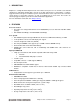
1. DESCRIPTION Morpheus is a Single Board Computer based on the Intel Celeron processor. It conforms to the PC/104 standard, an embedded standard that is based on the ISA and PCI buses and provides a compact, rugged mechanical design for embedded systems. PC/104 modules feature a pin and socket connection system in place of card edge connectors, as well as mounting holes in each corner. The result is an extremely rugged computer system fit for mobile and miniature applications.
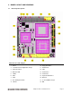
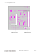
3. BOARD LAYOUT AND DRAWINGS 3.1 Board Layout Top View I/O Connectors and Jumpers 1. Power 10. Floppy Disk Drive 2. J5 Serial Port 2 Configuration Jumper 11. Parallel Port 3. Fan Power Input 12. LCD 4. Ethernet LED 13. Serial Port 2 5. Utilities 14. Serial Port 1 6. IrDA 15. Keyboard and Mouse 7. VGA 16. Ethernet 8. PC 104 Expansion Bus 17. J1 Clear CMOS Jumper 9. USB 0-1 18. IDE Morpheus CPU User Manual V1.
3.2 Board Layout Bottom View CompactFlash Socket DIMM Memory Socket Morpheus CPU User Manual V1.
4. JUMPER and I/O HEADERS J1 CMOS Jumper This jumper is used to clear CMOS RAM. This will restore the BIOS settings to factory default upon power up. J5 Serial Port2 Jumper This jumper is used to set serial protocol for Serial Port 2. Users can select between RS-232, 422, and 485. VGA This is a 16-pin I/O header for VGA connection. Users can obtain VGA output by connecting the female end of the VGA connector to this header and connecting the other end to the monitor.
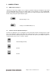
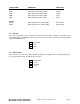
5. JUMPER SETTINGS 5.1 CMOS Jumper Settings J1 Jumpering J1 will reset the CMOS. If users experience problems booting up the Morpheus they should reset the CMOS RAM, which will restore the BIOS settings to factory defaults. To clear the CMOS RAM, power the board down, install the jumper as shown, wait a few seconds, then put the jumper back into the default setting. Then power up the Morpheus again. Default Setting (1-2 on) Setting to clear CMOS RAM (2-3 on) 5.
6. SYSTEM I/O 6.1 Serial Port Connectors Morpheus supports serial protocols RS-232, RS-422, and RS-485. Serial port 1 supports RS-232 only and serial port 2 supports RS-232/422/485. J5 configures the serial protocol for port 2. Information concerning J5 can be found on page 7. When connecting cables, connect the side with the red stripe to pin 1 on the Morpheus. Using the cable supplied in the cable kit C-MOR-KIT, the DB-9 connector will provide the standard DTE pinout for a PC serial port.
SIGNAL NAME DEFINITION DIRECTION RS-422: TXD+ TXDRXD+ RXD- Differential Transmit Data (HIGH) Differential Transmit Data (LOW) Differential Receive Data (HIGH) Differential Receive Data (LOW) Output Output Input Input RS-485: DATA+ DATA- Differential Transceiver Data (HIGH) Differential Transceiver Data (LOW) Bi-directional Bi-directional 6.2 CPU Fan This connector provides power to the CPU fan cooling system. The fan is strongly recommended on the North Bridge chip on the 650MHz model.
6.4 VGA Pin 11 is keyed for easy, error-free connection. When connecting the VGA cable, align the side with the red stripe to pin 1 and attach the .2mm header to the Morpheus. Connect the cable’s DB15 female connector to the monitor’s DB15 male connector for video output to monitor. Diamond Systems’ cable kit C-MOR-KIT includes a cable for this connector. Red Blue GND GND Vcc KEY HSYNC VDCLK 6.
6.6 IDE The connector connects IDE devices to the primary IDE channel and supports up to 2 IDE devices. The cable provided has connectors for 2mm 44-pin IDE devices and 0.1-inch 40-pin IDE devices. Connect most standard desktop hard disks, CD-ROM, etc to the 0.1 inch 40-pin IDE header on the cable. Attach laptop hard disks, flash disks, etc. to the 2mm 44-pin header on the cable. To connect the cable to the header, connect the side with the red stripe to pin 1.
6.7 Floppy Disk Drive This header is keyed to provide error-free connection. Morpheus supports up to two floppy drive connections simultaneously. To connect the provided cable to the header, attach the side with the red stripe to pin 1. Diamond Systems provides a floppy drive ribbon cable. GND GND GND #Write data #Write gate #Track 0 #Write protect #Read data #Head select #Disk change 6.
6.10 PS/2 Keyboard and Mouse Diamond Systems provides cables for keyboard and mouse 1 KB_DATA 2 GND 3 MS_DATA 4 KB_CLK 5 +5V 6 MS_CLK 6.11 Parallel Port The connector is keyed for error-free connection. When connecting the cable attach the side with the red stripe to pin 1. Diamond Systems’ cable kit C-MOR-KIT includes a cable for this connector.
6.13 Ethernet (100 Base-Tx) This connector is keyed for error-free connection. When connecting the cable to the header, align the side with the red stripe to pin 1. Diamond Systems’ cable kit C-MOR-KIT includes a cable for this connector. TX+ RX+ NC NC GND 1 3 5 7 9 2 4 6 8 10 TXNC RXGND KEY 6.14 Utilities This utility connector provides multiple functions for users. It provides functionalities such as reset, hard disk activity LED, and external speaker.
7. SYSTEM RESOURCES This section details the system resources including assignment of IRQ, I/O, and DMA. 7.
7.
04D0 – 04D1 PCI bus 0778 – 077F ECP Printer Port (LPT1) 0CF8 – 0CFF PCI bus 4000 – 407F PCI bus 4080 – 40FF PCI bus 5000 – 501F PCI bus 6000 – 607F PCI bus E000 – E007 Primary IDE controller (dual FIFO) E000 – E00F VIA Bus Master PCI IDE Controller E008 – E00F Secondary IDE controller (dual FIFO) E400 – E41F VIA Tech 3038 PCI to USB Universal Host Controller E800 – E81F VIA Tech 3038 PCI to USB Universal Host Controller EC00 – ECFF Realtek RTL8139/810x Family Fast Ethernet NIC Morp
8. ACCESSORIES Part Number MOR-400 MOR-650 C-MOR-KIT MEM-128-01 MEM-256-01 MEM-512-01 PS-5V-MOR ACC-IDEEXT FD-32-XT FD-64-XT FD-128-XT Description Morpheus PC/104 CPU, Celeron 400MHz Morpheus PC/104 CPU, Celeron 650MHz Morpheus Cable Kit (see page 19) 128MB RAM SODIMM for Morpheus 256MB RAM SODIMM for Morpheus 512MB RAM SODIMM for Morpheus AC Adapter, Universal in, 5VDC / 6A out, for Morpheus IDE Extender Board + 2 IDE cables (see below) 32MB Flashdisk, Extended Temp. 64MB Flashdisk, Extended Temp.
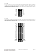
Figure 2. Morpheus Cable Kit Item Description 1 Keyboard and mouse cable 2 USB cable 3 VGA cable 4 IDE cable 5 Parallel port cable 6, 7 Serial port cables (2 included in kit) 8 Floppy drive cable 9 Ethernet cable Morpheus CPU User Manual V1.
9. QUICK START GUIDE This section will describe the steps necessary to get the Morpheus up and running quickly. 9.1 General Setup This section describes the initial setup that will be identical no matter which operating system or IDE configuration you choose to use. 1) Remove the Morpheus board from its packaging. 2) Install the mounting kit standoffs into the PC/104 mounting holes located at each corner of the board. This ensures that the board will not touch the surface beneath it.
9.4 Booting into Linux or Microsoft Windows This section describes how to setup Morpheus in preparation for a Linux or Windows install from an installation CD-ROM onto a laptop IDE hard drive. 1) Connect the IDE extender board to IDE channel. 2) Connect a CD-ROM drive jumpered for the slave position to the IDE extender board through the 40-pin cable. 3) Connect power to the CD-ROM drive. 4) Connect a laptop hard drive jumpered for master position to the second slot of the 44-pin cable.