CRYSTAL-MM-HP PC/104 Format SoundBlaster Pro Compatible High-Power Stereo Audio Module User Manual V2.0 © Copyright 2007 Diamond Systems Corporation 1255 Terra Bella Ave Mountain View, CA 94043 Tel (650) 810-2500 Fax (650) 810-2525 techinfo@diamondsystems.com www.diamondsystems.
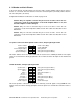
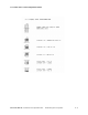
CONTENTS 1. FEATURES AND SPECIFICATIONS 3 2. BOARD DIAGRAM 4 3. I/O HEADER AND JACK PINOUTS 5 J3: Speaker connections with optional volume control, 2x5-pin right-angle header................................. 5 J4: Main I/O header, 2x10-pin right-angle header .................................................................................... 5 J8 and J13: Mono and PC speaker input/output, standard 1x6-pin right-angle header ........................... 6 J5 & J6: Stereo 3.5mm jacks.................
1. Features and Specifications Crystal-MM-HP is a dual-channel audio module for PC/104 embedded systems. It provides 16-bit stereo recording and playback with sample rates up to 44.1kHz. Features include full-duplex (simultaneous record and playback) capability, plug and play configuration, multiple input and output channels, multiple input and output user connection options, on-board 6-channel mixer, and built-in 20-voice FM synthesizer compatible with the Yamaha OPL3.
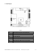
2.
3. I/O Header and Jack Pinouts In the header pinouts described below, note that the audio speaker amplifier outputs appear on three headers: J3, J4, and J5. Also note that Line In has two connection points (J4 and J6) and Line Out has two connection points (J4 and J5). Configuration information for all headers is shown on pages 8-10. Caution: Only one Speaker connection may be used at one time.
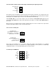
J8 and J13: Mono and PC speaker input/output, standard 1x6-pin right-angle header PC Speaker Out Mono Out Mono In Agnd PC Speaker In Dgnd 1 2 3 4 5 6 This header provides standard PC speaker in (2-pin) and out (4-pin) connections on a single header. The user may connect the PC speaker either to this point or to the main CPU connection point. The Mono In/Out signals are available only on versions of the board with the ES1869 chip.
4. Hardware Configuration Quick List of Configuration Options Base address options: 220, 230, 240, 250 Hex; Selected via plug and play configuration Interrupt levels: 5, 7, 9, 10, 11, 12, 15; Selected via plug and play configuration DMA levels: 0, 1, 3; Selected via plug and play configuration Volume control: A. Full volume, volume controlled in software only. B. External stereo potentiometer control plus software control.
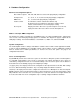
J9: Base Address / Interrupt Level / DMA Level Configuration Select one configuration from the upper 3 choices AND one configuration from the lower 2 choices. J10: Speaker Volume Control Configuration CRYSTAL-MM-HP User Manual v2.0 September 2007 Diamond Systems Corporation P.
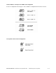
J11: 3.5mm Stereo Jack Configuration Header CRYSTAL-MM-HP User Manual v2.0 September 2007 Diamond Systems Corporation P.
5. Installation Before installing the board in your computer, make the following configuration selections: Select the desired interrupt options with jumper block J9. The default setting is IRQ E = 11, IRQ F = 12. Select the desired plug and play ROM option with jumper block J9. The default setting is internal ROM. Select the desired volume control option with jumper block J10. The default setting is Internal. Select the desired stereo jack configuration with jumper block J11.
6. Specifications Input and Output Specifications Mono microphone input: Input voltage range: Input impedance: 10mV to 125mV p-p 30KΩ min, 100KΩ max Stereo CD input: Input voltage range: Input impedance: 0V to 4V p-p 30KΩ min, 100KΩ max Stereo line / aux inputs: Input voltage range: Input impedance: 0V to 4V p-p 30KΩ min, 100KΩ max Stereo line / aux outputs: Output voltage range: Output impedance: 0V to 3.5V p-p 30KΩ typical PC speaker input: TTL input from CPU Stereo speaker output: 0.