
Corporation Personal Computer User Manual


Pegasus Fast Start Guide 7460572 Rev A Page 5 of 12
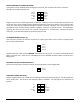
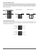
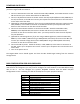
SERIALPORTCONNECTOR(COM1)
Thisconnectorprovidesaccesstothe2serialportsfromtheCPUchip.Port1isRS‐232onlyandPort2
maybejumper‐configuredforRS‐232,RS‐422orRS‐485protocols.In RS‐422/485mode,theport may
have a jumper‐selectable 120
‐ohm termination resistor across the RX pins and jumper‐selectable pull‐
up/pull‐downresistorsontheTX/RXlines.TheRXresistorsareconfiguredsothattheportreadsbacka
0whenitisopencircuit.
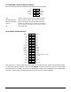
RS‐232Configuration RS‐422Configuration RS‐485configuration
Port1 DCD1 1 2 DSR1
RXD1 3 4 RTS1
TXD1 5 6 CTS1
DTR 1 7 8 RI1
Ground 9 10 Ground
Port2 DCD2 11 12 DSR2NC 11 12 NC NC 11 12 NC
RXD2 13 14 RTS2TX+ 13 14 TX‐ RTX+ 13 14 RTX‐
TXD2 15 16 CTS2RX+ 15 16 RX‐ NC 15 16 NC
DTR 2 17 18 RI2NC 17 18 NC NC 17 18 NC
Ground 19 20 GroundGround 19 20 Ground Ground 19 20 Ground
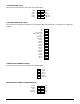
USBCONNECTORS(USB1andUSB2)
TheseconnectorsprovideaccesstothefourUSB2.0ports.Theshieldpinistiedtosystemground.The
key positions are missing to match the key position in the cable to prevent misconnection.Both
connectorshavethesamepinout.
Ground 1 2 +5V
Channel0Data+ 3 4 Channel0Data‐
Key 5 6 Ground
Ground 7 8 +5V
Channel1Data+ 9 10 Channel1Data‐
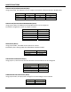
Ground
1 2 +5V
Channel2Data+ 3 4 Channel2Data‐
Key 5 6 Ground
Ground 7 8 +5V
Channel3Data+ 9 10 Channel3Data‐