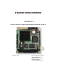
GF Rhodeus-LC Low Power AMD Geode™ LX800 PC/104 CPU Module with CRT/LCD, LAN and CF User’s Manual Copyright 2008 Diamond Systems Corporation 1255 Terra Bella Ave. Mountain View, CA 94043 Tel (650) 810-2500 www.diamondsystems.
Index Table of Contents Chapter 1 - Introduction ....................................................1 1.1 Copyright Notice .............................................................2 1.2 About User’s Manual .....................................................2 1.3 Warning .............................................................................2 1.4 Replacing the lithium battery ......................................3 1.5 Technical Support ..........................................................
Index COM1/ COM2: Serial Port Connector ....................20 CFD1: CompactFlash II Socket ..............................21 2.3 The Installation Paths of CD Driver ......................... 22 Chapter 3 - BIOS ................................................................23 3.1 BIOS Introduction ........................................................ 24 3.2 BIOS Setup .................................................................... 24 3.3 Standard CMOS Features .....................................
Introduction 1 Chapter 1 Introduction Chapter 1 - Introduction -1-
Introduction 1.1 Copyright Notice All Rights Reserved. The information in this document is subject to change without prior notice in order to improve the reliability, design and function. It does not represent a commitment on the part of the manufacturer. Under no circumstances will the manufacturer be liable for any direct, indirect, special, incidental, or consequential damages arising from the use or inability to use the product or documentation, even if advised of the possibility of such damages.
Introduction 1.4 Replacing the lithium battery Incorrect replacement of the lithium battery may lead to a risk of explosion. The lithium battery must be replaced with an identical battery or a battery type recommended by the manufacturer. Do not throw lithium batteries into the trashcan. It must be disposed of in accordance with local regulations concerning special waste. 1.
Introduction 1.6 Warranty This product is warranted to be in good working order for a period of two years from the date of purchase. Should this product fail to be in good working order at any time during this period, we will, at our option, replace or repair it at no additional charge except as set forth in the following terms. 7KLV ZDUUDQW\ GRHV QRW DSSO\ WR SURGXFWV GDPDJHG E\ PLVXVH PRGL¿FDWLRQV accident or disaster.
Introduction 1.7 Packing List 1 x Rhodeus-LC 1 x CD-ROM 1 x Quick Installation Guide If any of the above items is damaged or missing, contact your vendor immediately. 1.
Introduction 6SHFL¿FDWLRQ Form Factor PC/104 CPU module Processor AMD Geode™ LX800 Cache 64K L1 cache and 128K L2 cache Chipset AMD LX800 + CS5536 System Memory 1 x 200 pins DDR SO-DIMM up to 1GB SDRAM VGA/ LCD Controller AMD Geode LX series CPU integrated VGA controller with 2D Engine (Shared memory Max.
Introduction 1.
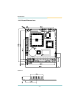
Introduction Unit:mm -8-
Installation 2 Chapter 2 Installation Chapter 2 - Installation -9-
Installation 2.1 Block Diagrams VGA LCD Analog R.G.B.
Installation 2.
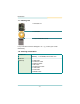
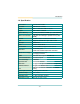
Installation Jumper / Connector Quick Reference Jumpers Label Function JRS1 COM2 RS-232/422/485 Select JBAT1 CMOS Jumper Settings Connectors DIMM1 200 pins DDR SDRAM DIMM Socket PC104_1 PC/104 for ISA Interface KBM1 PS/2 Keyboard and Mouse VGA1 CRT Display LCD1 TTL LCD Panel Connector COM1 ~ COM2 Serial Ports CON1 RS-422/485 Output IR1 Infrared (IR) Connector LPT1 Parallel Port LAN1 LAN Ethernet Connector LLED1 LAN LED Connector USB1 USB 1/2 Connector PWR1 Power Connector Sma
Installation KBM1: Keyboard & Mouse Connector (1) Connector type: 2.0mm pitch 1x6 pins wafer connector Pin Description 1 KB_DATA 2 GND 3 MS_DATA 4 KB_CLK 5 KB_VCC 6 MS_CLK 1 LAN1: Fast Ethernet Connector (2) Pin Description Pin Description 1 TX+ 2 TX- 3 RX+ 4 N/C 5 N/C 6 RX- 7 N/C 8 N/C 9 GND 10 N/C (Key) Connector type: 2.
Installation IDE1: 44 pins IDE Connector (3) Connector type: 2.
Installation PC/104: PC/104 ISA Interface (5) 1 B 2 3 B 2 3 A 1 A Pin D0 D1 D2 D3 D4 D5 D6 D7 D8 D9 D10 D11 D12 D13 D14 D15 D16 D17 D18 D19 Description GND MEMCS16# IOCS16# IRQ10 IRQ11 IRQ12 IRQ15 IRQ14 DACK0# DREQ0 DACK5# DREQ5 DACK6# DREQ6 DACK7# DREQ7 +5V MASTER# GND GND 0 C 19 C 0 D 19 D Pin C0 C1 C2 C3 C4 C5 C6 C7 C8 C9 C10 C11 C12 C13 C14 C15 C16 C17 C18 C19 Description GND SBHE# LA23 LA22 LA21 LA20 SA19 SA18 SA17 MEMR# MEMW# SD8 SD9 SD10 SD11 SD12 SD13 SD14 SD15 GND Pin A1 A2 A3 A4 A5 A6
Installation JRS1: COM 2 RS-232/422/485 Select (6) ,W FDQ EH FRQ¿JXUHG &20 WR RSHUDWH LQ 56 56 RU 56 PRGH Connector type: 2.00mm pitch 2x3 pin header. Select 1-2 3-4 5-6 RS-232 (Default) ON OFF OFF RS-422 OFF ON OFF RS-485 OFF OFF ON 1 2 1 2 1 2 5 6 5 6 5 6 LLED1: LAN LED indicators (7) Connector type: 2.54mm pitch 1x4 pin header.
Installation IR1: Infrared Connector (9) Connector Type: 2.54mm pitch 5 pins header Pin Voltage 1 +5V 2 N/C 3 IRRX 4 GND 5 IRTX 1 VGA1: CRT Connector (10) Connector type: 2.0mm pitch 2x5 pin header Pin Description Pin Description 1 RED 2 GREEN 3 BLUE 4 N/C 5 GND 6 GND 7 GND 8 GND 9 N/C 10 GND 11 N/C (Key) 12 VDDAT 13 HSYNC 14 VSYNC 15 VDCLK 16 N/C 1 2 15 16 USB1: USB Connector (11) USB1 supports two USB 2.
Installation FDD1: 20 pins FDD Connector (12) Connector type: 2.
Installation LPT1: 20 pins Parallel Port Connector (14) Connector type: 2.0mm pitch 2x10 pin header Pin Description Pin Description 1 STROBE 2 AFD 3 PTD0 4 ERROR 5 PTD1 6 INIT 7 PTD2 8 SLIN 9 PTD3 10 GND 11 PTD4 12 GND 13 PTD5 14 GND (Key) 15 PTD6 16 BUSY 17 PTD7 18 PE 19 ACK 20 SELECT 1 19 CON1: RS-422/ 485 Output Connector (15) Connector type: 2.
Installation LCD1: TTL LCD Connector (16) Connector type: DF-13-40DP-1.
Installation CFD1: CompactFlash II Socket CFD1 does not support hot swap.
Installation 2.
BIOS 3 Chapter 3 BIOS Chapter 3 - BIOS - 23 -
BIOS 3.1 BIOS Introduction The Award BIOS (Basic Input/Output System) installed in your computer system’s. The BIOS provides for a standard device such as disk drives, serial ports and parallel ports. It also adds password protection as well as special VXSSRUW IRU GHWDLOHG ¿QH WXQLQJ RI WKH FKLSVHW FRQWUROOLQJ WKH HQWLUH V\VWHP 3.2 BIOS Setup The Award BIOS provides a Setup utility program for specifying the system FRQ¿JXUDWLRQV DQG VHWWLQJV 7KH %,26 520 RI WKH V\VWHP VWRUHV WKH 6HWXS utility.
BIOS 3.3 Standard CMOS Features “Standard CMOS Features” allows you to record some basic hardware FRQ¿JXUDWLRQV LQ \RXU FRPSXWHU V\VWHP DQG VHW WKH V\VWHP FORFN DQG error handling. If the CPU card is already installed in a working system, you will not need to select this option.
BIOS IDE Primary HDDs / IDE Secondary HDDs The onboard PCI IDE connectors provide Primary and Secondary channels for connecting up to four IDE hard disks or other IDE devices. (DFK FKDQQHO FDQ VXSSRUW XS WR WZR KDUG GLVNV WKH ¿UVW LV WKH ³0DVWHU´ DQG the second is the “Slave”. 3UHVV (QWHU! WR FRQ¿JXUH WKH KDUG GLVN 7KH VHOHFWLRQV LQFOXGH $XWR 0DQXDO DQG 1RQH 6HOHFW µ0DQXDO¶ WR GH¿QH WKH GULYH LQIRUPDWLRQ PDQXDOO\ You will be asked to enter the following items.
BIOS Halt On 7KLV ¿HOG GHWHUPLQHV ZKHWKHU RU QRW WKH V\VWHP ZLOO KDOW LI DQ HUURU LV detected during power up. All errors (default) Whenever the BIOS detects a non-fatal error, the system will stop and you will be prompted. No errors The system boot will not be halted for any error that may be detected. All, But Keyboard The system boot will not be halted for a keyboard error; it will stop for all other errors.
BIOS 3.4 Advanced BIOS Features Quick Power On Self Test :KHQ HQDEOHG WKLV ¿HOG VSHHGV XS WKH 3RZHU 2Q 6HOI 7HVW 3267 DIWHU the system is turned on. If it is set to Enabled, BIOS will skip some items. Setting: Enabled (Default), Disabled. First/ Second Boot Device 7KHVH ¿HOGV GHWHUPLQH WKH GULYH WKDW WKH V\VWHP VHDUFKHV ¿UVW IRU DQ operating system. The options available include Setting: Floppy, LS120, HDD-0, SCSI, CDROM, HDD-1, ZIP100, USB-FDD, USB-ZIP, USB-CDROM, USB-HDD, LAN and Disabled.
BIOS Boot Up NumLock Status It allows you to activate the NumLock function after you power up the system. Setting: On (Default), Off. Security Option It allows you to limit access to the System and Setup. When you select System, the system prompts for the User Password every time you boot up. When you select Setup, the system always boots up and prompts for the Supervisor Password only when the Setup utility is called up. Setting: Setup (Default), System.
BIOS 3.5 Advanced Chipset Features CAS Latency Time It allows CAS latency time in HCLKs as 2 or 2.5. The system board designer VKRXOG VHW WKH YDOXHV LQ WKLV ¿HOG GHSHQGLQJ RQ WKH '5$0 LQVWDOOHG 'R QRW FKDQJH WKH YDOXHV LQ WKLV ¿HOG XQOHVV \RX FKDQJH VSHFL¿FDWLRQV RI WKH installed DRAM or CPU. Setting: 2.5 (Default), 2. Interleave Select It allows you to Use the Interleave Select option to specify how the cache memory is interleaved. Setting: LOI (Default), HOI.
BIOS XOR MB0 Setting: Disabled (Default), Enabled. XOR Bit Select Setting: 18 (Default), 19, 20, 21. Video Memory Size In order to determine how much memory is allocated to the video graphics device. Setting: None, 8M (Default), 16M, 32M, 64M, 128M, 254M. Output display In order to specify the display devices the system is connected to. Setting: Flat Panel, CRT (Default), Panel & CRT.
BIOS 3.6 Integrated Peripherals OnChip IDE Devicev >>> On-Chip IDE Channel 1 The integrated peripheral controller contains an IDE interface with support for two IDE channels. Select Enabled to activate each channel separately. Setting: Disabled, Enabled (Default).
BIOS IDE Primary Master/Slave PIO It allows your system HDD controller to run faster. Rather than having the BIOS issue with a series of commands that transferring to or from the disk drive, PIO (Programmed Input/Output) allows the BIOS to communicate with the controller and CPU directly. When Auto is selected, the BIOS will select the best available mode. Setting: Auto (Default), Mode 0, Mode 1, Mode 2, Mode 3, Mode 4.
BIOS SuperIO Device >>> Onboard FDC Controller Select “Enabled” if you wish to use it. Select “Disabled” if you don’t wish to use it. Setting: Disabled, Enabled (Default). Serial/ Onboard Parallel Port It allows you to select the onboard serial and parallel ports with their addresses. Serial Port 1 3F8/IRQ4 (Default) Setting: Serial Port 2 2F8/IRQ3 (Default) Parallel Port 378H/IRQ7 (Default) UART Mode Select It determines the UART 2 mode in your computer. Setting: IrDA, ASKIR, Normal (Default).
BIOS UR2 Duplex Mode Setting: Full, Half (Default). Use IR Pins Setting: RxD2,TxD2 , IR-Rx2Tx2 (Default). Parallel Port Mode Setting: SPP (Default) EPP ECP ECP+EPP Normal EPP Mode Select Setting: EPP1.9, EPP1.7 (Default) ECP Mode Use DMA Setting: 1, 3 (Default).
BIOS IT8888 ISA Decode IO >>> It allows you to use the IT8888 ISA Decode IO menu to set the IO memory range for the onboard ISA. Decode I/O Space 0/ 1/ 2/ 3/ 4/ 5 It allows you to allocate system resources to the ISA bridge and to enable the function correctly. Setting: Disabled, Enabled (Default). Decode I/O Speed 0/ 1/ 2/ 3/ 4/ 5 It allows you to specify the speed of the ISA bus. Setting: Subtractive Speed, Slow Speed, Medium Speed, Fast Speed.
BIOS Decode I/O Address 0/ 1/ 2/ 3/ 4/ 5 [15:4] It allows you to allocate an address to the ISA bus. The address may range from 0001 to 0FFF. Decode I/O Size 0/ 1/ 2/ 3/ 4/ 5 It allows you to specify the size of the ISA bus. Setting: 1 Byte, 2 Bytes, 4 Bytes, 8 Bytes, 16 Bytes, 32 Bytes, 64 Bytes, 128 Bytes. IT8888 ISA Decode Memory >>> It allows you to use the IT8888 ISA Decode Memory to set the resources for the onboard ISA bus.
BIOS Decode Memory Speed 0/ 1/ 2/ 3 It allows you to specify the memory speed of the ISA bus. Setting: Subtractive Speed, Slow Speed, Medium Speed, Fast Speed. Decode Memory Addr. 0/ 1/ 2/ 3 [23: It allows you to allocate a memory address to the ISA bus. The address may range from 0001 to 0FFF. Decode Memory Size 0/ 1/ 2/ 3 It allows you to specify the memory size of the ISA bus. Setting: 16 KB, 32 KB, 64 KB, 128 KB, 256 KB, 512 KB, 1MB, 2MB.
BIOS 313 3&, &RQ¿JXUDWLRQV PNP OS Installed It allows you to enable the PNP OS Install option if it is supported by the OS installed. Setting: No (Default), Yes. 5HVHW &RQ¿JXUDWLRQ 'DWD ,W DOORZV \RX WR GHWHUPLQH ZKHWKHU WR UHVHW WKH FRQ¿JXUDWLRQ GDWD RU QRW Setting: Disabled (Default), Enabled. Resources Controlled By 7KLV 3Q3 %,26 FDQ FRQ¿JXUH DOO RI WKH ERRW DQG FRPSDWLEOH GHYLFHV ZLWK WKH use of a PnP operating system. Setting: Auto(ESCD) (Default), Manual.
BIOS IRQ Resources ,W DOORZV \RX WR FRQ¿JXUH WKH ,54 '0$ 5HVRXUFHV Memory Resources ,W DOORZV \RX WR FRQ¿JXUH WKH 0HPRU\ 5HVRXUFHV PCI/VGA Palette Snoop Some non-standard VGA display cards may not show colors properly. It allows you to set whether or not MPEG ISA/VESA VGA cards can display with PCI/VGA. When “Enabled”, a PCI/VGA can display with an MPEG ISA/VESA VGA card. When “Disabled”, a PCI/VGA can not display with an MPEG ISA/VESA VGA card. Setting: Disabled (Default), Enabled.
BIOS 3.
BIOS 3.9 Load Optimized Defaults ,W DOORZV \RX WR ORDG WKH GHIDXOW YDOXHV WR \RXU V\VWHP FRQ¿JXUDWLRQ 7KH default setting is optimal and enabled all high performance features.
BIOS 3.10 Set Password Using Password to set a password that will be used exclusively on the system. To specify a password, highlight the type you want and press . The Enter Password: message prompts on the screen. Type the password, XS WR HLJKW FKDUDFWHUV LQ OHQJWK DQG SUHVV (QWHU! $QG WKH V\VWHP FRQ¿UPV your password by asking you to type it again. After setting a password, the screen automatically returns to the main screen.
BIOS 3.11 Save & Exit Setup Typing “Y”, you will quit the setup utility and save all the changes into the CMOS memory. Typing “N”, you will return to Setup utility.
BIOS 3.12 Exit Without Saving 7\SLQJ ³<´ ZLOO TXLW WKH 6HWXS XWLOLW\ ZLWKRXW VDYLQJ WKH PRGL¿FDWLRQV Typing “N” will return you to Setup utility.
BIOS 3.13 BIOS Beep Sound code list Beep Sound Message 1 short (Beep) System booting is normally 2 short (Beep) CMOS setting error 1 long - 1 short (Beep) DRAM error 1 long - 2 short (Beep) Display card or monitor connected error 1 long - 3 short (Beep) Keyboard error 1 long - 9 short (Beep) ROM error Long (Beep) continuous DRAM hasn’t inset correctly Short (Beep) continuous POWER supply has problem 3.
BIOS 3.
BIOS 20h 21h 22h 23h 24h 25h 26h 27h 28h 29h 2Ah 2Bh 2Ch 2Dh 2Eh 2Fh 30h 31h 32h 33h 34h 35h 36h 37h 38h 39h 3Ah 3Bh 3Ch 3Dh 3Eh 3Fh 40h 41h 42h 43h 44h 45h 46h Reserved HPM initialization (notebook platform) Reserved Check validity of RTC value; Load CMOS settings into BIOS stack. If CMOS checksum fails, use default value instead; Prepare BIOS resource map for PCI & PnP use. If ESCD is valid, take into consideration of the ESCD's legacy information; Onboard clock generator initialization.
BIOS 47h 48h 49h 4Ah 4Bh 4Ch 4Dh 4Eh 4Fh 50h 51h 52h 53h 54h 55h 56h 57h 58h 59h 5Ah 5Bh 5Ch 5Dh 5Eh 5Fh 60h 61h 62h 63h 64h 65h 66h 67h 68h 69h 6Ah 6Bh 6Ch 6Dh 6Eh 6Fh Initialize EISA slot Reserved Calculate total memory by testing the last double last word of each 64K page; Program writes allocation for AMD K5 CPU Reserved Reserved Reserved Reserved Program MTRR of M1 CPU; initialize L2 cache for P6 class CPU & program cacheable range; Initialize the APIC for P6 class CPU; On MP platform, adjust the cac
BIOS 70h 71h 72h 73h 74h 75h 76h 77h 78h 79h 7Ah 7Bh 7Ch 7Dh 7Eh 7Fh 80h 81h 82H 83H 84h 85h 86h 87h 88h 89h 90h 91h 92h 93h 94h 95h 96h FFh Reserved Reserved Reserved (QWHU $:')/$6+ (;( LI $:')/$6+ (;( LV IRXQG LQ ÀRSS\ GLYH and ALT+F2 is pressed Reserved Detect and install all IDE devices: HDD, LS120, ZIP, CDROM...
Appendix 4 Chapter 4 Appendix Chapter 4 - Appendix - 51 -
Appendix 4.1 I/O Port Address Map Each peripheral device in the system is assigned a set of I/O port addresses which also becomes the identity of the device. The following table lists the I/O port addresses used.
Appendix 000003F8 - 000003FF Communications Port 00000778 - 0000077B Printer Port 00000A79 - 00000A79 ISAPNP Read Data Port 00000D00 - 0000FFFF PCI Bus 0000FC00 - 0000FCFF Realtek RTL8139/810x family Fast Ethernet NIC 0000FF00 - 0000FF0F Standard Dual Channel PCI IDE Controller 4.2 Interrupt Request Lines (IRQ) Peripheral devices use interrupt request lines to notify CPU for the service required. The following table shows the IRQ used by the devices on board.
Appendix 4.