
Instruction manual


Copyright ©2006 Diamond Traffic Products
ALL RIGHTS RESERVED
7
2.b. Sensor and Sensor Modes
The Phoenix II supports Road Tube Air Switches, Inductive Loops, Remote Inputs, Piezo Resistive and Piezo Electric
Inputs. Road Tubes, Remote Inputs, and Piezo Sensors are considered “axle” sensors, since they are activated by
individual axles. Inductive Loops are considered “presence” sensors, since they become activated by the metal in the
vehicle passing over, and deactivate when the vehicle leaves. The Remote input will support any type of sensor which
will give a momentary switch closure.
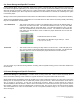
Since there are variations with each sensor (for example, Inductive Loops will have slightly different amounts of
inductance), the Phoenix II performs automatic tuning or adjustment for all sensors except for Piezo Resistive by default.
The user must tune Piezo manually or enable auto piezo calibration during setup using the Phoenix II keypad or a
PC/laptop computer and Centurion Software. See Section 3.d.3 for more information.
When in Per-Vehicle (raw) storage or Binned storage modes, seven types of sensor arrangements (sensor modes)
may be selected:
Axle-Axle
-
Two axle sensors either piezo or road tube.
Loop-Loop
-
Two loop sensors.
Axle-Loop-Axle
-
Two axle sensors and one loop sensor.
Loop-Axle-Loop
-
Two loop sensors and one axle sensor.
Loop-Axle-Axle
-
One loop and two axle sensors.
Loop-Axle-Axle-Loop
-
Two loop and two axle sensors (speed calculated using axle sensors)
Loop-Axle-Loop-Axle
-
Two loop and axle sensors alternating (speed calculated using axle sensors)
In addition to the seven sensor array types, with the I-Loop board (version 4.00 and higher) the loop inputs can also be
used as a OC/Relay or contact closure style presence inputs to allow external sensors to feed into the Phoenix II loop
inputs. This allows connection to other detectors such as microwave/radar, other inductive loop outputs, video, or other
presence style outputs to be used for count and classification.
In Count Storage mode, you can select either a Loop Sensor or an Axle Sensor. In Timestamp (Sensor) Storage
mode, you can select a Loop Sensor, an Axle Sensor, or Both.
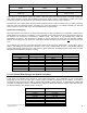
The way sensors are divided up among the lanes depends on the storage mode (Raw, Binned, etc.) and the sensor
mode (Axle-Axle, Loop-Loop, etc.). Table 1 shows the divisions of the sensors.
Table 1
Count & Sensor Storage
Raw & Binned Storage
Lane Number
Axle (Piezo)
Loop
Axle (Piezo)
Loop
#1
1
1
1 & 2
1 & 2
#2
2
2
3 & 4
3 & 4
#3
3
3
5 & 6
5 & 6
#4
4
4
7 & 8
7 & 8
#5
5
5
n/a
9 & 10
#6
6
6
11 & 12
#7
7
7
13 & 14
#8
8
8
15 & 16
#9
n/a
9
2 & 1 (directional)
2 & 1 (directional)
#10
10
4 & 3 (directional)
4 & 3 (directional)
#11
11
5 & 6 (directional)
5 & 6 (directional)
#12
12
7 & 8 (directional)
7 & 8 (directional)
#13
13
n/a
10 & 9 (directional)
#14
14
12 & 11 (directional)
#15
15
14 & 13 (directional)
#16
16
15 & 16 (directional)