
Instruction manual

Copyright ©2006 Diamond Traffic Products
ALL RIGHTS RESERVED
27
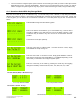
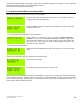
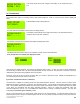
Set this value to indicate the spacing in between your sensors. This can be set
from 0.2 feet (6cm) to 99.9 feet. See Section 3.d (Sensors) for recommended
spacing.
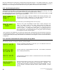
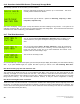
This question is asked if you selected any combination that includes Loops in the
Sensor selection screen. You must enter the Length of the loop used for this
lane. If you have entered Loop-Loop, it is the length of the Second Loop. The
Phoenix II uses this information in calculating vehicle length. If you are doing
length classification, and the Phoenix is giving over or under lengths, use this
value to correct the length.
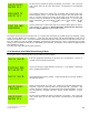
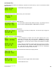
Use the arrow keys to select which type of Per-Vehicle (Raw) Data you wish to
collect (Section 2). Options are Normal Raw Data, Enhanced Raw, Raw with
Bins, and Enhanced & Bins. Press ENTER to select.
The system will now go into a lane test mode. If you have loops connected, the system will give the message “Tuning
Loops” and then “Waiting For Any Vehicle…”. Each lane may now be tested, with the data displayed on the LCD as
vehicles are registered. Note – If you have selected a Sensor Mode which uses a loop and no loops are connected; or if
there is a failure in a loop, the system will display “Unconnected Loop Check:nnnn” with “n” being the loop (or loops)
which you have requested for use but is not detectable by the Phoenix II. At that point, connect up the missing loops and
press ENTER to try again.
From here, the system asks the final start questions.
4.c.4 Questions Asked With Binned Storage Mode
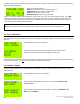
The program asks the following questions for each lane you have enabled.
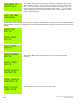
Enter the appropriate information for this lane, up to 15 characters. This Info is
normally used to indicate lane direction.
Use the arrow keys to toggle between Yes and No. If it is enabled, a directional
lane is created (see Section 2).
Used if Directional has been created. If Directional mode has not been enabled,
this will not be asked.
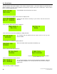
Select the Sensor Mode you wish to use. Options in Per-Vehicle (Raw) Mode are
Axle-Axle, Loop-Loop, Axle-Loop-Axle and Loop-Axle-Loop. Important – this
question will only be asked if you have at least one loop board installed. If you do
not, the Phoenix II assumes Axle-Axle sensors (Tubes, Remotes, or Piezo
Sensors).
Set this value to indicate the spacing in between your sensors. This can be set
from 0.2 feet (6cm) to 99.9 feet. See Section 3.d (Sensors) for recommended
spacing.