
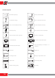
Specifications


70
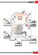
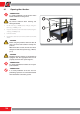
5.6.1 Read the capacity diagrams
- Name and model of the vehicle (Fig. 4-F0300, pos. 1)
- Equipment model (Fig. 4-F0300, pos. 2)
For additional information, consult the “Capacity diagrams
key” chapter.
- Code of the Capacity diagram (Fig. 4-F0300, pos. 3)
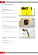
- Maximum capacity of the equipment ( F i g . 4 - F 0 3 0 0 , p o s . 4 )
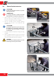
The maximum capacity of the equipment is also marked by
the relative sticker on the equipment itself (Fig. 1-F0300).
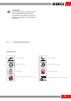
- Boom angle (Fig. 4-F0300, pos. 5)
The angle of the boom is indicated via inclinometer on the
left side, at the end of the boom (Fig. 2-F0300) or on the
display of the anti-tipping device (if present).
- Boom extension (Fig. 4-F0300, pos. 6)
The boom extension is marked with the alphabet letters (“A”,
“B”, “C”, “D”, etc.). The same letters are reported on stickers on
the boom extension, so that the user in the cab knows the
boom extension by reading the letters on it (Fig. 3-F0300).
- Vehicle operating mode (Fig. 4-F0300, pos. 7)
For additional information, consult the “Capacity diagrams
key” chapter.
- Load height from the ground (Fig. 4-F0300, pos. 8)
- Horizontal distance of the load from the vehicle (Fig.
4-F0300, pos. 9)
- Weight of the load (Fig. 4-F0300, pos. 10)
- Position of the vehicle (Fig. 4-F0300, pos. 11)
1- F0300
2- F0300
3- F0300