| STOP DON'T PANIC SSE [TN DH9 HYDROPONIC KIT AND ASSEMBLED HOT WATER INSTALLATION MANUAL Ww Water Mark se JAS
www.dleselheat.com.
diesel www.dleselheat.com.au Installation Guidelines Diesel heat is providing this installation manual to help make sure your installation is successful. Please read this guide carefully as many product issues can result from improperly performed installations. We can't take responsibility for performance loss, product damage or failure that has resulted from poor installation practices or a failure to follow recommended guidelines .
diesel www.dleselheat.com.au o Facilitates installation in tight spaces. * Moves the furnace to a location where noise can be better managed. # For marine installations, enables the furnace to be moved to a location where the exhaust is easier to install. When remote-mounting the furnace: « Take appropriate precautions to stop external hose damage where hoses pass through walls or bulkheads.
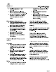
diesel www.dleselheat.com.au Do not hang the tank on Its securing tabs. it must be supported from underneath. Hot Water Service Tank Mounting Requirements: eo Must be mounted vertically with filler cap on top. « Filler cap should be accessible to fill the system and periodically check coolant level. important Design Considerations e No diesel appliances like ingesting dust. Consider air inlet locations and system location to minimize or prevent dust being sucked into the combustion inlet.
diesel www.dleselheat.com.au Set Up The Tank The tank is shipped with the tempering valve installed and these connections are pressure tested prior to shipping. We do not recommend moving or adjusting the tempering valve as the connections require special sealant and tightening. For the KIT, 18mm hose tails are provided for the coolant inlet and outlet. All connections on the tank for coolant need to be sealed with either thread tape or Maalox 58-11 to ensure there are no coolant leaks.
diesel www.dleselheat.com.au Hot water only Installations. For hot water only installations, connectors 3 and 4 should be blocked with the supplied plugs. However, the bypass hole blocking ring should not be installed. Installations with 1 fan head located at or below 0.5m above the top of the coolant tank. For installations with only 1 fan head located within 1.5m of the tank at or below 0.
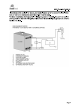
diesel www.dleselheat.com.au Installations with multiple fan heads, fan heads located up to 1m above the level of the tank or where the fan head Is more than 1.5m from the tank. For these installations, the bypass hole blocking ring must be installed. This prevents coolant passing back into the tank and significantly increases the available pump pressure to drive the coolant circulation. DHS SCHEMATIC SETUP: FATHEAD >» 0.
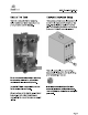
diesel www.dleselheat.com.au DHE SCHEMATIC SE TUR: MULTIPLE PAN HERDS MUNG VALE HYDRO FURNACE: COOLANT SPUME COLE WATER QUEENLY, d OT WATER OUTLET EXHAUST, NATIONAL FAN BEATING HEAD: OPTIONAL SHUT ORE VALVE EXTERNAL BYPASS VALVE BYPASS HOLE BLOCKING RING EC SE COR = In this scenario, bypass valves must be installed on each fan head so that if the coolant is shut off in any one fan head, coolant circulation is not stopped in the whole system.
diesel www.dleselheat.com.au Plumbing the Coolant Hoses The furnace to hot water service tank plumbing should be done with rubber or silicone hoses of 20mm ID and secured with quality hose clamps. The hose and clamps provided in the Cyberspace DSE HS3 kit are ideal for this purpose. The hot water service to fan heating head plumbing should be done with 16mm [D rubber hoses and secured with quality hose clamps.
diesel www.dleselheat.com.au Fan Heater Installation The hoses connecting the cabin fan heater are connected directly to the DH tank ports. The cabin fan heaters should be plumbed with 16mm hose for short runs {less than 2m) or 16mm insulated PEX for longer runs. To mount the cabin heater: * Remove the front face of the heater and measure the outlet surface area. Cut the appropriate hole in the board. e Sandwich the kick board between the face and the main heater housing.
diesel www.dleselheat.com.au Controlling The Air Temperature Temperature control can be achieved via 3 methods. The first method is via an inline valve with the coolant return line from the fan head. Partially closing the valve will restrict the coolant circulation and reduce the heat given off by the fan head. The VA200 fan head has the valve built in, while other fan heads can have a ball valve installed behind them.
diesel www.dleselheat.com.au Tempering Valve Controlling Water Temperature When the system has been muted on and has warmed up, the water coming straight from the DH hot water service will be approximately 70-75 degrees. The tempering valve not only controls the outlet temperature but will increase the usable hot water capacity. The volume of coolant at 70-75 degrees is directly related to how much hot water is available at 45-50 degrees.
diesel www.dleselheat.com.au Fuel System Follow the Cyberspace H5E HS3 technical manual for fuel system installation. Ensure the pump is installed with the correct orientation. Like 45: t interrelation postie behests 8° 15% is net af £ Prestidigitation petition-withle Se age £59 35% SF Initialization FOR wt ThE ahi: 257 10 BM eld It is advisable to install the pump as close as possible to the fuel source so it pushes the fuel instead of sucking it.
diesel www.dleselheat.com.au Fuel Source The DHE can be connected to an auxiliary fuel tank, to a day tank or to a connection point on the main fuel system or generator fuel system. When connecting to main fuel systems in boats or motor homes, it is important to ensure that the fuel take off point is not pressurized (downstream of any feed pumps) and that there are no opportunities for air to enter the fuel lines.
diesel www.dleselheat.com.au RV Exhaust The exhaust system on an RV consists of 2 lengths of exhaust and a muffler. The exhaust should be installed in a manner that ensures it cannot dislodge or come into contact with any electrical wiring, water pipes, etc., as it is hot enough to melt plastics. The exhaust should have a length of pipe before the muffler and generally at least 30cm of pipe after the muffler, as this helps to manage noise.
diesel www.dleselheat.com.au Marine Exhaust Always use high-quality marine stainless steel exhaust systems and clamps to ensure no exhaust gasses are vented inside the boat. The total maximum length of the marine exhaust is 2m. Always install the exhaust with a goose neck on the inside of a hull fitting fo prevent water washing back into the exhaust system. Note: The exhaust system reaches temperatures of up to 300°C.
diesel www.dleselheat.com.au Combustion Air The DHS KIT ships with the furnace combustion air inlet pipe and combustion silencer separated from the fum ace. This is to enable the user fo install the components in the most appropriate way. For marine applications or instances in RVs where the fum ace is installed inside a locker or cupboard, it is acceptable to install the combustion air inlet inside the engine room or locker.
diesel www.dleselheat.com.au Commissioning It is a time consuming and messy operation to rectify any bad joints or leaks after the system is filled with coolant. The coolant system operates at approximately 5-psi, so check that all hose connections are secure and all hoses are kink free before filling the system with coolant. When the system is 100% installed, insert the fuses in the power line and power up the furnace. Coolant Pump Priming Remove the radiator cap on the DH9 hot water service.
diesel www.dleselheat.com.au initial Startup Once the coolant pump is primed, leave the switch on and the furnace will attempt to start. The furnace will not start until the fuel pump and fuel line have primed. A furnace start process involves 2 separate start attempts and takes approx. 6 minutes. During each start attempt, the coolant pump runs, the combustion fan revs up and down and the fuel pump attempts to pump fuel. At the end of a start process (after 2 attempts), the furnace will shut down and wait.
diesel www.dleselheat.com.au Coolant Furnace Operation Turn on the furnace with the on\off switch. After approximately 3 seconds, the coolant circulating pump will come on. The glow pin and fuel pump will then come on and the fum ace will start its combustion cycle. Once the fum ace obtains full combustion, it will continue to produce heat on full power until the coolant temperature reaches 70°C. This will take approximately 8 minutes, depending on the ambient temperature.
diesel www.dleselheat.com.au Commissioning Troubleshooting Problem Things to Check On initial switch on, furnace does nothing. Check fuel pump connection wires are properly inserted into connector and connector is properly plugged into the pump. See specific instructions on the Diesel heat D5E Ancillary Wiring Instructions. Check coolant pump wires are properly connected. Check power supply and fuses. Check furnace is wired directly to batteries.
diesel www.dleselheat.com.au System heats up but fan heads do not get hot. Check fan head shut off valves are open. If using a valved bypass valve, ensure the bypass valve is partially closed. If using a valveless bypass valve, check the bypass valve is on the same level as the fan head. Check tank plumbing and bypass arrangements are in accordance with schematics in these instructions. Fan heads get hot but do not blow hot air. Check fans are wired with correct polarity.