
Product Manual

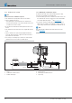


Picture 20
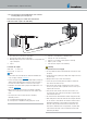
1 Tank connection (di = Ø 2mm, da = Ø 4mm) – installed in the
vehicle's own tank fitting
2 Adapter (Ø 7.5 / 3.5mm) – connected to the vehicle's own tank
fitting, at a socket Ø 8mm, used to pass through the intake line
(fuel pipe 4 x 1) up to just before the bottom of the tank.
3 Metering pump
4 Fuel filter – only required for contaminated fuel
5 Fuel pipe, 4x1 (di Ø 2mm)
6 Adapter ( Ø 4.5 / 3.5mm)
7 Fuel hose, 3.5 x 3 (di Ø 3.5mm), approx. 50mm long
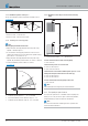
Permissible line lengths
Intake side: a = max. 2 m
Pressure side: b = max. 6 m
Note
Fuel supply mounting instructions,
see Picture 20
Items 4 and 5 are not included in the “Universal installation kit”
scope of supply. Order No.
see page 11.
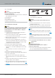
Connect fuel pipe (Item 5) to the heater using adapter (Item 6). The
adapter (Item 6) with diameter 4.5 mm fits on the fuel sockets of
the heater. The smaller diameter 3.5mm fits on the fuel pipe.
Use two screw clamps Ø 11 to secure the adapter Ø 7.5 / 3.5 mm
(Item 2) (tightening torque: 1
+0.2
Nm).
Installation of a fuel filter (Item 4) requires two adapters Ø5 / 3.5,
Order No.
see page 11.
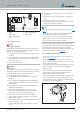
When installing tank connection (Item 1), maintain a minimum
distance of 5
±2
mm from the end of the riser to the bottom of the
tank.
26 25.2933.90.0001.0A EN | 06.2018
Technical Description | Hydronic S3 Economy