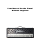
User Manual for the Diezel Herbert Amplifier
Table of Contents Chapter One: Safety and Warranty 1.1 Safety Warnings 1.2 Warranty Information Chapter Two: Using Your Herbert 2.1 Mains Connections, Power and Standby 2.1.1 Mains/connect to power outlet 2.1.2 Power up, Warm up, Standby off 2.1.3 Power tube caution 2.1.4 Operating Temperature 2.1.5 Power Tube Information Chapter Three: Peripheral Connections 3.1 Front Panel Connections 3.1.1 Signal In 3.1.2 Connection Information 3.1.3 Cable Selection 3.2 Rear Panel Connections 3.2.1 Send/Return Loop 3.
Chapter Five: Power Amplifier 5.1 Tone and Volume of the Power Amplifier 5.1.1 Master Volume 5.1.2 Presence 5.1.3 Deep 5.2 Power Amplifier Tubes 5.2.1 Function 5.2.2 Selection 5.2.3 Life Span Chapter Six: Functions and Switches 6.1 6.2 6.3 6.4 6.5 6.6 6.7 Programming Herbert Manual Channel Selection Mid Cut on/off Loop on/off Mute on/off Master 2 Store Chapter Seven: Midi 7.1 MIDI 7.2 MIDI In 7.3 MIDI Thru 7.4 MIDI Communication 7.4.1 Omni Mode 7.4.2 Single Channel Mode – automatic Channel Recognition 7.
Chapter One: Safety and Warranty 1.1 Safety Warnings We would like to stress the importance of the following points, for reasons of your personal safety, product longevity and product liability. Do not use the amplifier in or near wet locations Do not store the amplifier in damp or wet locations Do not operate the Amplifier on voltages other than those designated on the rear panel of the amplifier. Do not open the panels of the amplifier. No user serviceable parts inside.
1.2 Warranty 5 years to the original owner with proof of purchase. Power Tubes and Pre Amp tubes are covered for 3 months to the original owner. The amps will be tracked via both Diezel USA and Diezel Germany recorded sales beginning 1/20/2009. ALL REPAIR WORK MUST BE DONE BY A DIEZEL CERTIFIED TECHNICIAN. Not following this procedure will VOID WARRANTY.
Chapter Two: Using Your Herbert 2.1 Mains Connections, Power and Standby 2.1.1 Mains/Connection to Power Outlet Please make sure that both switches (Power and Standby) are in the off position before connecting to the Mains circuit. Verify line voltage before connecting the power cord. Never start Herbert without speakers being connected to the proper terminals. (See 3.2.8) 2.1.2 Power up, Warm up, Standby off First turn the Power switch to on (facing up). The indicator will light up.
2.1.4 Operating Temperature It will take a little more time after warm-up until everything inside the amp is working in sync and to it’s fullest potential. A trained ear will notice a slightly warmer tone and better complexity in tone after playing the amp for a short while. It’s like warming up before running a marathon. Get it? 2.1.5 Power Tube Life The power tubes of your amplifier are subject to a certain aging process.
Chapter Three: Peripheral Connections 3.1 Front Panel Connections 3.1.1 The input jack (“IN”) The input jack receives your Electric Guitar signal by means of a shielded guitar cord with 1/4” mono style plug. Your guitar cord is an important part of your signal chain and its quality and construction type clearly affect the overall tone of your rig. Try and buy the best quality guitar cord that you can or want to afford. Call us if you have doubts and need recommendations.
3.2 Rear Panel Connections 3.2.1 Send/Return Loop The System consists of 3 separate Loops. It allows creation of effects path in either serial, parallel, or switched configurations. The individual channel volume controls determine the signal strength at the send jacks. The range is - ... to +10dB. The output impedance is 4.7 kOhm. If you want to use the loops, then connect the “Send” to the input of the Effects unit. Be sure and adjust the input level of the effects unit to the amplifiers level.
3.2.3 Switch-able Loop as additional Volume Control Those of you who can live without processors in the parallel loop can use this loop for a second master volume for each channel. To do this, just loop a short 1/4” cable from the switch-able send to parallel loop return. Now you can choose a second master volume by turning the mix control past 1:00 PM to full open, and push the ‘ Loop” button to activate your second master volume.
3.2.7 Compensated Out A frequency corrected signal will leave this jack if you connect it to a mixer or recording device. Use it to quietly compose or send an auxiliary signal to a console etc. Always make sure that your amp is connected to either a loudspeaker or a load (i.e. THD HotPlate). 3.2.8 Speaker Connections Herbert has 5 speaker jacks: 1 for a 16-Ohm load, 2 for 2 16-Ohm loads or 1 8Ohm load, and 2 for 2 8-Ohm loads or 1 4-Ohm load.
3.3 MIDI Connections 3.3.1 MIDI In Midi in receives “program change” orders from commonly available midi pedals and control systems. The Herbert is able to supply phantom power to your midi pedal via a 7-prong DIN midi cable. This can help unclutter your stage system and rids the artist of these pesky power supplies. Pin 1 and 6 is ground (-) Pin 3 and 7 is hot (+) The voltage is 9-12V AC or DC, which is acceptable for 98% of all midi pedals. Maximum power usage of the pedal cannot exceed 800mA (0.
Chapter Four: Three Pre-Amplifiers 4.1 Pre-Amplifiers and their Functions The Diezel Herbert comes equipped with 3 different and totally independent preamps. This allows the artist to play every conceivable musical style without having to make major changes to his or her amplifier. The preamps are voiced to deliver the 3 most wanted guitar tone flavors: 1-Clean, 2-Crunch/Heavy 3- Lead.
4.1.4 Mid Cut The section Mid Cut incorporates controls for Intensity and Level. Designed for friends of Heavy or Nu-Metal type musical styles, the Intensity control attenuates low midrange at approximately 400Hz. To compensate for the inevitable volume loss when activating this feature, one can bring the volume level back up with the Level Control. This Mid Cut function is MIDI assignable and can therefore be assigned to any or all of the three channels.
4.3 Microphonics and Bad Noises The overall performance of pre-amp tubes is easily influenced by mechanical factors from the outside. This would manifest itself by a sudden feedback sound with high pitch. The input stage is especially suspect to this phenomenon. If one encounters microphonic tube behavior, then the first tube should be checked as a rule. Pre-Amplifier tubes can also cause hum or other bad noises, like crackling or ticking.
Chapter Five: Power Amplifier 5.1 Tone and Volume of the Power Amplifier 5.1.1 Master Volume As the name suggests, this controls the overall, global volume of the amplifier. For your enjoyment, there is also a second programmable master volume control, which allows volume adjustments via remote control while you are playing. Both controls are laid out so that even a low-performance effects unit can be used and amplified in the loops. 5.1.2 Presence This knob controls frequencies over 3KHz.
5.2 Power Amplifier Tubes 5.2.1 Function As the name suggests, the power amp section is the part of the amplifier that produces output power, measured in watts. Preamp signals are sent to the power amp(s), which amplifies this signal to a level that is acceptable for loudspeakers. Guitar amplifiers utilize several different types of power amps, which differ in output power and tone. We chose the tube type power amplifier for its tried-andtrue performance and familiar tonal behavior. 5.2.
Chapter Six: Functions and Switches 6.1 Programming the Herbert It is quite easy to program your Diezel Herbert and, also, easy to explain. Pushing the “Store” toggle switch twice must follow each change in the MIDI program. After the first click, the selected blue LED lights will blink. Click on the switch again and your program is in memory. Each of the 128 programs (patches, program changes) can be changed as often as is desired. 6.
6.3 Mid Cut On/Off The switching function “Mid Cut” is applicable to all channels. The Mid Cut is active when the corresponding LED is lit. 6.4 Loop On/Off This function activates a device that is connected to the switch-able loop. 6.5 Mute On/Off “Mute” silences the beast. “Tuner Out” stays active. Makes sense, no? 6.6 Master 2 On/Off Master 2 can be used for all channels, much like the Mid Cut function. 6.7 Store As discussed earlier, this is the universal programming button.
Chapter Seven: MIDI 7.1 MIDI MIDI is an acronym for Musical Instruments Digital Interface and is an internationally accepted communications system between musical instruments (and processors and computers) of all kinds. We will only need to learn a small portion of this “language” to use the Herbert and its peripheral MIDI partners. We are going to learn only about “program change”. 7.2 MIDI In MIDI In is a 7-pole DIN jack.
7.4.2 Single Channel Mode – Automatic Channel Recognition Your Herbert can automatically recognize the pedal’s send/receive channel. To get your amp into the mood (or mode) for this, push and hold “Mute” and then activate any program change button on your MIDI pedal. The amp will look for a program change and recognize the channel it is being sent on. Then it will switch to this channel and stay there as soon as you let go of “Mute”. 7.4.
Chapter Eight: Footswitch The optional Columbus footswitch can be connected via the rear panel mounted XLR jack. The Columbus will not recognize functions selected from the front panel. Chapter Nine: Maintenance and Cleaning 9.1 Cleaning Never use a wet method of cleaning the amplifier, i.e. any amplifier. Usually it is sufficient to wipe down the outside of the amp with a slightly moist cleaning rag. Do not use abrasive cleaning chemicals.
9.3 Tube Change Tube changes are only to be undertaken by authorized service personnel. If power tubes with different values then the original ones are to be installed, then the amplifier must be re-biased before operation can be resumed. The amplifier uses a three circuit bias system. It is quick and easy to accomplish biasing, but involves removing the chassis and use of specialized equipment for measuring currents inside the amplifier. Only trained professionals should attempt this procedure.