
User's Manual
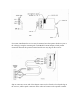

Connect wires as follows:
(a) White wire to terminal “1” or “24v”
(b) Black wire to terminal “2” or “Relay”
(c) Red wire to terminal “3” or “Common” ( Radio Power )
(d) Connect push button wires to terminal “1” and “2” (See Figure #2)
Where power for the radio receiver is not available from the operator order a Model
5192-01 power transformer adapter for connection between the operator and the remote
receiver.
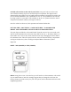
SETTING THE ( “RECEIVER” ) CODE SWITCH - TO WORK WITH MODEL
5010 AND MODEL 5012 SINGLE BUTTON TRANSMITTERS
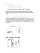
Use your finger to slide the “code switch hatch” from the receiver for access to the code
switch. On the transmitter the entire front lower half of the case ( “ the battery hatch” ) is
removeable. Use a coin or the curved end of the visor clip to disengage the lower half of
the transmitter front. This will expose both the code switch and the battery compartment
(See Figure #3).
Model – 5010 (300mHz) or 5012 (310mHz)