Digi Connect™ Wi-Wave 802.11 b/g Hardware Reference .................................................................. Part number/version: 90000797_B Release date: March 2010 www.digiembedded.
©2010 Digi International Inc. Printed in the United States of America. All rights reserved. Digi, Digi International, the Digi logo, a Digi International Company, Jump Start Kit, ConnectCore, NET+, NET+OS and NET+Works are trademarks or registered trademarks of Digi International, Inc. in the United States and other countries worldwide. All other trademarks are the property of their respective owners.
Contents ..................................................................... Chapter 1:About the Module..................................................................7 Features 7 What’s on the module? 8 Digi Connect Wi-Wave 802.11 b/g module edge connector 8 Digi Connect Wi-Wave 802.11 b/g module edge connector: Pinout 9 U.FL connectors 9 USB peripheral controller 10 802.
Debug breakout header signal map 21 W_DISABLE# signal 22 U.FL and RP-SMA connectors 23 U.FL connectors 23 U.FL cables 23 RP-SMA connectors 24 For more information 24 Chapter 3: Using the Antenna ............................................................ 25 Necessary Conditions for Integration 25 Connect Wi-Wave 802.11 b/g antenna configurations 26 General information 26 Antenna switch 26 Cable Specification: U.FL/W.FL to RP-SMA 26 Attributes 26 Antenna specifications: 802.
Using this Guide ..................................................................... This guide provides information about the Digi Connect Wi-Wave 802.11 b/g embedded core module. Conventions used in this guide This table describes the typographic conventions used in this guide: This convention Is used for italic type Emphasis, new terms, variables, and document titles. monospaced type Filenames, pathnames, and code examples. Digi information .....................................................
Contact information For more information about your Digi products, or for customer service and technical support, contact Digi International. To contact Digi International by Use Mail Digi International, Inc. 11001 Bren Road East Minnetonka, MN 55343 U.S.A 6 World Wide Web www.digiembedded.com Eservice Support www.digi.com/support/eservice/login.jsp Telephone (U.S.) (952) 912-3444 or (877) 912-3444 Telephone (other locations) +1 (952) 912-3444 or +1 (877) 912-3444 Digi Connect Wi-Wave 802.
Chapter 1:About the Module T he Digi Connect Wi-Wave module is an 802.11b/g WLAN communications module for use in embedded applications. The module is a single circuit card packaged in a PCI Express Mini Card form factor, and supports all the RF, analog, and digital circuitry necessary to implement WLAN functionality.
What’s on the module? What’s on the module? .................................................................................. Digi Connect WiWave 802.11 b/g module edge connector 8 The Digi Connect Wi-Wave 802.11 b/g module edge connector is a 52-pin connector whose pinout follows the standard PCI Express Mini Card edge connector pinout as stated in the PCI Express Mini Card Electromechanical Specification, Revision 1.
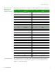
Digi Connect WiWave 802.11 b/g module edge connector: Pinout The module edge connector is configured as shown (signal direction w.r.t Wi-Wave): Pin Type WLAN Mini Card signal Pin Type WLAN Mini Card signal 1 n/a No connect 2 In Vcc_3.
USB peripheral controller USB peripheral controller .................................................................................. The module uses a peripheral USB controller to interface to either a full speed or high speed USB 2.0 link. The link first tries to communicate to the host system board at the high speed USB rate (480 Mbps). If not successful, the link reverts to the full speed USB rate (12 Mbps). This link is used for all communication between the module and the host system board.
..... Voltage regulators Voltage regulators .................................................................................. The module takes in 3.3V±9% (3.00V to 3.60V) as its main input power. This power is filtered and used as a 3.3V supply to portions of the digital logic. This power also acts as input to dedicated on-board voltage regulators. Voltage monitor — Reset generator ..................................................................................
Power Power Requirements 12 Module state Current Composition 3/3V Input Suspended xx mA Wireless Receive 240 mA Wireless Transmit 420 mA Digi Connect Wi-Wave 802.11 b/g Hardware Reference, Rev.
Chapter 2:About the Development Board T he development board is designed for product evaluation and development purposes. In addition to the Digi Connect Wi-Wave 802.11 b/g connector, the development board provides several breakout connectors and interfaces. What’s on the development board .................................................................................. Features Digi Connect Wi-Wave 802.
ABOUT THE DEVELOPMENT BOARD What’s on the development board The development board Unpopulated components 14 There are components on the development board that are currently not populated. These components allow the development board to be used in other applications. Digi Connect Wi-Wave 802.11 b/g Hardware Reference, Rev.
..... ABOUT THE DEVELOPMENT BOARD Digi Connect Wi-Wave802.11 b/g module connector, J52 Digi Connect Wi-Wave802.11 b/g module connector, J52 .................................................................................. Place the Digi Connect Wi-Wave 802.11 b/g module into the connector and support bracket, J52, on the development board. The Digi Connect Wi-Wave 802.11 b/g module connector is a 52-pin connector that conforms to the PCI Express Mini Card Electromechanical Specification, Rev. 1.
ABOUT THE DEVELOPMENT BOARD Digi Connect Wi-Wave802.11 b/g module connector, J52 Note: 16 Signal direction w.r.t PCIe Mini Card. Pin Type Signal Pin Type Signal 1 n/a No connect 2 In Vcc_3.
LEDs ..... ABOUT THE DEVELOPMENT BOARD LEDs .................................................................................. LEDs: DS3-DS7 LED DS1 The switching regulator is adjusted to output +3.3VDC ± 5% or better. LED DS1 lights up when the regulator outputs +3.3V power. See “Power supply” on page 19 for more information. LED DS2 LED DS2 lights up when the host system supplies power over the USB bus.
ABOUT THE DEVELOPMENT BOARD Switches and reset functionality Switches and reset functionality .................................................................................. Voltage monitor The development board provides a power supply voltage monitor and reset generator. When the +3.3V regulated supply voltage drops below 2.93V, the reset signal — RESET# — is asserted for a minimum of 140 msec. This signal is connected to the Digi Connect Wi-Wave 802.
Power supply ..... ABOUT THE DEVELOPMENT BOARD Power supply .................................................................................. The development board provides a 3.3VDC switching power supply. Either a bench power supply or an AC wall adapter supplies input power to the development board. The required input voltage range is 9–30VDC. Input power jack, J3 The input power jack, J3, is a barrel connector that accepts 9-30 VDC. The power jack is labeled J3 on the development board.
ABOUT THE DEVELOPMENT BOARD USB peripheral interface, J4 USB peripheral interface, J4 .................................................................................. USB peripheral jack, J4 20 The USB Type B connector, J4, is the primary communications interface to the development board. The USB bus is routed from the USB peripheral jack to the appropriate module connector pins. Digi Connect Wi-Wave 802.11 b/g Hardware Reference, Rev.
Debug breakout header, P21 ..... ABOUT THE DEVELOPMENT BOARD Debug breakout header, P21 .................................................................................. The debug breakout header’s primary purpose is to provide access to the W_DISABLE# signal. The W_DISABLE# signal is typically used as a hardware means to disable RF transmissions from the module without software intervention. Debug breakout header signal map www.digiembedded.
ABOUT THE DEVELOPMENT BOARD Debug breakout header, P21 W_DISABLE# signal The active low W_DISABLE# signal is on pin 20 of the debug breakout header. GND signals are positioned adjacent to the W_DISABLE# signal on pins 18 and 19. To assert the W_DISABLE# signal to the module, place a jumper between either pins 18 and 20 or pins 19 and 20. As an alternative, you can drive this pin with a low voltage TTL or CMOS driver. When asserted, W_DISABLE# lights the DISABLE LED, DS3. 22 Digi Connect Wi-Wave 802.
U.FL and RP-SMA connectors ..... ABOUT THE DEVELOPMENT BOARD U.FL and RP-SMA connectors .................................................................................. U.FL connectors The development board has two U.FL connectors that pair with two RP-SMA connectors. U.FL connector X5pairs with RP-SMA connector J1;U.FL connector X4 pairs with RP-SMA connector J2. U.FL cables The development kit includes two U.FL-to-U.FL cables that can be used to connect the module and development board.
ABOUT THE DEVELOPMENT BOARD U.FL and RP-SMA connectors RP-SMA connectors RP-SMA Wi-Fi antennas are attached to the two RP-SMA connectors, J1 and J2. Single antenna configuration: Attach an RP-SMA antenna to RP-SMA connector J1. Dual antenna configuration: Attach RP-SMA antennas to both RP-SMA connectors J1 and J2. For more information 24 For information about the antenna(s), see Chapter 3, “Using the Antenna.” Digi Connect Wi-Wave 802.11 b/g Hardware Reference, Rev.
Chapter 3:Using the Antenna T he Digi Connect Wi-Wave 802.11 b/g development board supports one type of antenna: 29000146 ANT, WHIP 2.4 GHz Dipole Attach the U.FL-to-U.FL cables, provided in the development kit, to both the module and the development board. There are two cables included; whether you use one cable or both depends on how you set up your antenna(s). Be sure that the antenna you use complies with the regulatory requirements of your region.
USING THE ANTENNA General information Connect Wi-Wave 802.11 b/g antenna configurations The Digi Connect Wi-Wave 802.11 b/g can transmit data or receive data, but not at the same time. Note: If only one antenna is used, it must be connected to Wi-Fi RP-SMA antenna connector J1. This is the Digi Connect Wi-Wave 802.11 b/g’s primary antenna. General information ..................................................................................
..... USING THE ANTENNA Antenna specifications: 802.11 a/b/g antenna 1 = U.FL 2 = RP-SMA Note: This module obtained its complete certification by using the cable described here. End users in North America should use a cable that matches these specs to maintain the module’s certification. Antenna specifications: 802.11 a/b/g antenna .................................................................................. Attributes www.digiembedded.com Attribute Band 1 Band 2 Frequency 2.4~2.5 GHz 5.
USING THE ANTENNA End User Manual: RF Exposure Statements Dimensions Note: Dimensions are provided for reference purposes only. The actual antenna might vary. End User Manual: RF Exposure Statements ..................................................................................
Appendix A: Specifications T his appendix provides Digi Connect Wi-Wave 802.11 b/g module specifications as well as safety statements and antenna specifics. Environmental specifications ..................................................................................
Mechanical dimensions – Differential Quadrature Phase Shift Keying (DQPSK) @ 2Mbps – BPSK @ 6 and 9 Mbps – QPSK @ 12 and 18 Mbps – 16-Quadrature Amplitude Modulation (QAM) @ 24 and 36Mbps – 64-QAM @ 48 and 54Mbps Frequency Bands – 2.412 to 2.472 GHz (ETSI) – 2.412 to 2.462 GHZ (FCC) Receiver Sensitivity 802.
..... Power requirements Power requirements .................................................................................. Parameter Limits Input voltage (Vcc) 3.3V±9% (3.00V to 3.60V) Input current 750mA max Input low voltage 0.0V
Module and development board dimensions Any external communications wiring you may install needs to be constructed to all relevant electrical codes. In the United States, this is the National Electrical Code Article 800. Contact a licensed electrician for details. Module and development board dimensions .................................................................................. Module dimensions Note: The measurements in this drawing are in inches. 1.181 +.00/-.01 .953 CL DETAIL A 1.
Development board dimensions Note: ..... Module and development board dimensions The measurements in this drawing are in inches. 3.000 .050" RAD MAX 2.095 AREA REMOVED .550 0 0 www.digiembedded.com 1.850 3.150 5.
Appendix B:Certifications T he Digi Connect Wi-Wave 802.11 b/g products comply with the standards cited in this section. FCC Part 15 Class B .................................................................................. Radio Frequency Interface (RFI) (FCC 15.105) The Digi Connect Wi-Wave 802.11 b/g embedded module has been tested and found to comply with the limits for Class B digital devices pursuant to Part 15 Subpart B, of the FCC rules.
CERTIFICATIONS FCC Part 15 Class B device must accept any interference received, including interference that may cause undesired operation. If the FCC ID is not visible when installed inside another device, then the outside of the device into which the module is installed must also display a label referring to the enclosed module FCC ID. This exterior label can use wording such as the following: Contains Transmitter Module FCC ID: MCQ-50M1746, IC: 1846A-50M1746. Modifications (FCC 15.
FCC Part 15 Class B ..... CERTIFICATIONS Declaration of Conformity (In accordance with FCC Dockets 96-208 and 95-19) Manufacturer’s Name: Digi International Corporate Headquarters: 11001 Bren Road East Minnetonka MN 55343 Manufacturing Headquarters: 10000 West 76th Street Eden Prairie MN 55344 Digi International declares, that the product: Product Name: Digi Connect Wi-Wave 802.
CERTIFICATIONS FCC Part 15 Class B International EMC Standards The Digi Connect Wi-Wave 802.11 b/g meets the following standards: Standards Emissions EN 55022 EN 300328 ICES-003 FCC Part 15 Subpart B Class B FCC Part 15 Subpart C Section 15.247 (FCC ID: MCQ-50M1746) IC RSS 210 Issue 6 and RSS GEN Issue 1 (IC: 1846A-50M1746) Immunity EN 55024 EN 301489-1-17 Safety UL 60950-1 IEC60950/EN 60950-1 CSA C22.2, No. 60950-1 37 Digi Connect Wi-Wave 802.11 b/g Hardware Reference, Rev.
Index ............................................................................... Numerics 2 dBi Dipole antenna 27-?? strength (radiation pattern) diagram 27 5.5 dBi Dipole antenna 27-28 attributes 27 dimensions 28 802.11b/g modes and channels 10 A antenna switch 26 antennas about 25-28 configurations 26 specifications 2 dBi Dipole 27 5.
Index pinout 9 J J1, input power jack 19 J4, USB peripheral jack 20 L LED DS1 17 LED DS2 17 LED DS3, DISABLE 17 LED DS4, WAN 17 LED DS5, LAN 17 LED DS6, PAN 17 LEDs debug (signal) breakout header 17 development board 17 module 11 M mechanical dimensions, module 30 module 802.