
User's Manual


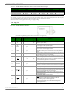
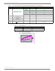
Table Of Contents
- 1. XTend RF Module
- 2. RF Module Operation
- 3. RF Module Configuration
- Programming Examples
- Command Reference Table
- Command Descriptions
- %V (Board Voltage) Command
- AM (Auto-set MY) Command
- AP (API Enable) Command
- AT (Guard Time After) Command
- BD (Interface Data Rate) Command
- BR (RF Data Rate) Command
- BT (Guard Time Before) Command
- CC (Command Sequence Character) Command
- CD (GPO2 Configuration) Command
- CF (Number Base) Command
- CN (Exit AT Command Mode) Command
- CS (GPO1 Configuration) Command
- CT (Command Mode Timeout) Command
- DB (Received Signal Strength) Command
- DT (Destination Address) Command
- E0 (Echo Off) Command
- E1 (Echo On) Command
- ER (Receive Error Count) Command
- FH (Force Wake-up Initializer) Command
- FL (Software Flow Control) Command
- FS (Forced Synch Time) Command
- FT (Flow Control Threshold) Command
- GD (Receive Good Count) Command
- HP (Hopping Channel) Command
- HT (Time before Wake-up Initializer) Command
- HV (Hardware Version) Command
- ID (Modem VID) Command
- KY (AES Encryption Key) Command
- LH (Wake-up Initializer Timer) Command
- MD (RF Mode) Command
- MK (Address Mask) Command
- MT (Multi-transmit) Command
- MY (Source Address) Command
- NB (Parity) Command
- PB (Polling Begin Address) Command
- PD (Minimum Polling Delay) Command
- PE (Polling End Address) Command
- PK (Maximum RF Packet Size) Command
- PL (TX Power Level) Command
- PW (Pin Wake-up) Command
- RB (Packetization Threshold) Command
- RC (Ambient Power - Single Channel) Command
- RE (Restore Defaults) Command
- RM (Ambient Power - All Channels) Command
- RN (Delay Slots) Command
- RO (Packetization Timeout) Command
- RP (RSSI PWM Timer) Command
- RR (Retries) Command
- RT (GPI1 Configuration) Command
- SB (Stop Bits) Command
- SH (Serial Number High) Command
- SL (Serial Number Low) Command
- SM (Sleep Mode) Command
- ST (Time before Sleep) Command
- TP (Board Temperature) Command
- TR (Transmit Error Count) Command
- TT (Streaming Limit) Command
- TX (Transmit Only) Command
- VL (Firmware Version - Verbose)
- VR (Firmware Version - Short) Command
- WA (Active Warning Numbers) Command
- WN (Warning Data) Command
- WR (Write) Command
- WS (Sticky Warning Numbers) Command
- API Operation
- 4. RF Communication Modes
- Appendix A: Agency Certifications
- Appendix B: Development Guide
- Appendix C: Additional Information

XTend™RFModule‐ProductManual
©2013DigiInternatonal,Inc. 6
*Ifthesupplyvoltageforagivenpowersettingislowerthantheminimumsupplyvoltagerequirement(asshowninTable1‐02),the
TXPowerOutputwilldecreasetothehighestpowerlevelsettinggiventhecurrentsupplyvoltage.
**1WPowerOutputisnotsupportedwhenusinga
3.3supplyvoltage.
Pin Signals
Figure1‐01. XTendRFModulePinNumbers
Tabl e1‐02. XTendRFModuleSpecifications‐Relativetouser‐selectedTXPowerOutput
Power Requirements (Supply voltage and TX currents relative to each TX Power Output option)
Transmit Power Output 1 mW 10 mW 100 mW 500 mW * 1 W *
Supply Voltage 2.8 - 5.5 VDC 3.0 - 5.5 VDC 4.75 - 5.5 VDC
Transmit Current (5 V) typical 130 mA 160 mA 270 mA 500 mA 680 mA
Transmit Current (3.3 V) typical 125 mA 150 mA 260 mA 600 mA **
Tabl e1‐03. PinSignalDescriptions
(Low‐assertedsignalsdistinguishedwithahorizontallineoversignalname.)
Pin
Number
Mnemonic I/O
High Impedance
during Shutdown
Must
Connect
Function
1GND- - yesGround
2VCCI - yes
Power: 2.8 - 5.5 VDC (Power supply ripple: +/- 250mV max @ 5V, 1A or +/-
125mV max @ 3.3V, 600mA.)
3
GPO2 /
RX LED
Oyes -
General Purpose Output 2: <Default (CD=2)> Pin is driven low. Refer to the CD
Command [p25] for other configuration options.
RX LED: Pin is driven high during RF data reception; otherwise, the pin is driven
low. Refer to the CD Command [p25] to enable.
4 TX
_PWR O yes -
Transmit_Power: Pin pulses low during RF transmission; otherwise, the pin is
driven high to indicate power is on and the module is not in Sleep or Shutdown
Mode.
5DIIyes yes
Data In: Serial data entering the module (from the UART host). Refer to the Serial
Communications [p10] section for more information.
6DOOyes -
Data Out: Serial Data exiting the module (to the UART host). Refer to the Serial
Communications [p10] section for more information.
7 SHDN
Ino yes
Shutdown: Pin is driven high during operation and low during Shutdown.
Shutdown enables the lowest power mode (~5 µA) available to the module. Refer
to the Shutdown Mode [p15] section for more information.
8 GPI2 / SLEEP I yes -
General Purpose Input 2: reserved for future use
SLEEP: By default, SLEEP is not used. To configure this pin to enable Sleep
Modes, refer to the Sleep Mode [p15], SM Command [p37] & PW Command [p33]
sections.
9
GPO1 / CTS
/
RS-485 TX_EN
Oyes -
General Purpose Output 1: reserved for future use
CTS
(Clear-to-Send): <Default (CS=0)> When pin is driven low, the UART host
is permitted to send serial data to the module. Refer to the Serial Communications
[p10] & CS Command [p26] sections for more information.
RS-485 Transmit Enable: To configure this pin to enable RS-485 half and full-
duplex communications. Refer to the Serial Communications [p10] & CS
Command [p26] sections.
10
GPI1 / RTS
/
CMD
Iyes -
General Purpose Input 1: reserved for future use
RTS
(Request-to-Send): By default, is not used. To configure this pin to
regulate the flow of serial data exiting the module, refer to the Serial
Communications [p10] & RT Command [p36] sections.
CMD (Command): By default, CMD is not used. To configure this pin to enable
binary command programming, refer to the Binary Commands [p18] & RT
Command [p36] sections.