
User's Manual


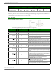
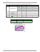
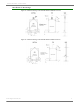
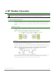
Table Of Contents
- 1. XTend RF Module
- 2. RF Module Operation
- 3. RF Module Configuration
- Programming Examples
- Command Reference Table
- Command Descriptions
- %V (Board Voltage) Command
- AM (Auto-set MY) Command
- AP (API Enable) Command
- AT (Guard Time After) Command
- BD (Interface Data Rate) Command
- BR (RF Data Rate) Command
- BT (Guard Time Before) Command
- CC (Command Sequence Character) Command
- CD (GPO2 Configuration) Command
- CF (Number Base) Command
- CN (Exit AT Command Mode) Command
- CS (GPO1 Configuration) Command
- CT (Command Mode Timeout) Command
- DB (Received Signal Strength) Command
- DT (Destination Address) Command
- E0 (Echo Off) Command
- E1 (Echo On) Command
- ER (Receive Error Count) Command
- FH (Force Wake-up Initializer) Command
- FL (Software Flow Control) Command
- FS (Forced Synch Time) Command
- FT (Flow Control Threshold) Command
- GD (Receive Good Count) Command
- HP (Hopping Channel) Command
- HT (Time before Wake-up Initializer) Command
- HV (Hardware Version) Command
- ID (Modem VID) Command
- KY (AES Encryption Key) Command
- LH (Wake-up Initializer Timer) Command
- MD (RF Mode) Command
- MK (Address Mask) Command
- MT (Multi-transmit) Command
- MY (Source Address) Command
- NB (Parity) Command
- PB (Polling Begin Address) Command
- PD (Minimum Polling Delay) Command
- PE (Polling End Address) Command
- PK (Maximum RF Packet Size) Command
- PL (TX Power Level) Command
- PW (Pin Wake-up) Command
- RB (Packetization Threshold) Command
- RC (Ambient Power - Single Channel) Command
- RE (Restore Defaults) Command
- RM (Ambient Power - All Channels) Command
- RN (Delay Slots) Command
- RO (Packetization Timeout) Command
- RP (RSSI PWM Timer) Command
- RR (Retries) Command
- RT (GPI1 Configuration) Command
- SB (Stop Bits) Command
- SH (Serial Number High) Command
- SL (Serial Number Low) Command
- SM (Sleep Mode) Command
- ST (Time before Sleep) Command
- TP (Board Temperature) Command
- TR (Transmit Error Count) Command
- TT (Streaming Limit) Command
- TX (Transmit Only) Command
- VL (Firmware Version - Verbose)
- VR (Firmware Version - Short) Command
- WA (Active Warning Numbers) Command
- WN (Warning Data) Command
- WR (Write) Command
- WS (Sticky Warning Numbers) Command
- API Operation
- 4. RF Communication Modes
- Appendix A: Agency Certifications
- Appendix B: Development Guide
- Appendix C: Additional Information

XTend™RFModule‐ProductManual
©2013DigiInternatonal,Inc. 7
*RFmodulehas10Kinternalpull‐upresistor
Note: When integrating the module with a Host PC board, all lines not used should be left disconnected (floating).
Electrical Characteristic
Figure1‐02. SystemBlockDiagram
BasicRFLinkbetweenHosts
The data flow sequence is initiated when the first byte of data is received in the DI Buffer of the
transmitting module (XTend RF Module A). As long as XTend RF Module A is not already receiving
RF data, data in the DI Buffer is packetized then transmitted over-the-air to XTend RF Module B.
Timing Specifications
Figure1‐03. TimingSpecifications(‘A’and‘B’refertoFigure1‐02)
11 CONFIG
/ RSSI
I* no -
Configuration: Pin can be used as a backup method for entering Command
Mode during power-up. Refer to the Command Mode [p17] section for more
information.
O* no -
Receive Signal Strength Indicator: By default, pin is used as an RSSI PWM
output after at the conclusion of the power-up sequence. Refer to the RP
Command [p35] for more information. The PWM output is 2.8V-level.
12-20 reserved / do not connect
Tabl e1‐03. PinSignalDescriptions
(Low‐assertedsignalsdistinguishedwithahorizontallineoversignalname.)
Pin
Number
Mnemonic I/O
High Impedance
during Shutdown
Must
Connect
Function