
User's Manual


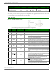
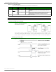
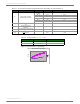
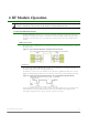
Table Of Contents
- 1. XTend RF Module
- 2. RF Module Operation
- 3. RF Module Configuration
- Programming Examples
- Command Reference Table
- Command Descriptions
- %V (Board Voltage) Command
- AM (Auto-set MY) Command
- AP (API Enable) Command
- AT (Guard Time After) Command
- BD (Interface Data Rate) Command
- BR (RF Data Rate) Command
- BT (Guard Time Before) Command
- CC (Command Sequence Character) Command
- CD (GPO2 Configuration) Command
- CF (Number Base) Command
- CN (Exit AT Command Mode) Command
- CS (GPO1 Configuration) Command
- CT (Command Mode Timeout) Command
- DB (Received Signal Strength) Command
- DT (Destination Address) Command
- E0 (Echo Off) Command
- E1 (Echo On) Command
- ER (Receive Error Count) Command
- FH (Force Wake-up Initializer) Command
- FL (Software Flow Control) Command
- FS (Forced Synch Time) Command
- FT (Flow Control Threshold) Command
- GD (Receive Good Count) Command
- HP (Hopping Channel) Command
- HT (Time before Wake-up Initializer) Command
- HV (Hardware Version) Command
- ID (Modem VID) Command
- KY (AES Encryption Key) Command
- LH (Wake-up Initializer Timer) Command
- MD (RF Mode) Command
- MK (Address Mask) Command
- MT (Multi-transmit) Command
- MY (Source Address) Command
- NB (Parity) Command
- PB (Polling Begin Address) Command
- PD (Minimum Polling Delay) Command
- PE (Polling End Address) Command
- PK (Maximum RF Packet Size) Command
- PL (TX Power Level) Command
- PW (Pin Wake-up) Command
- RB (Packetization Threshold) Command
- RC (Ambient Power - Single Channel) Command
- RE (Restore Defaults) Command
- RM (Ambient Power - All Channels) Command
- RN (Delay Slots) Command
- RO (Packetization Timeout) Command
- RP (RSSI PWM Timer) Command
- RR (Retries) Command
- RT (GPI1 Configuration) Command
- SB (Stop Bits) Command
- SH (Serial Number High) Command
- SL (Serial Number Low) Command
- SM (Sleep Mode) Command
- ST (Time before Sleep) Command
- TP (Board Temperature) Command
- TR (Transmit Error Count) Command
- TT (Streaming Limit) Command
- TX (Transmit Only) Command
- VL (Firmware Version - Verbose)
- VR (Firmware Version - Short) Command
- WA (Active Warning Numbers) Command
- WN (Warning Data) Command
- WR (Write) Command
- WS (Sticky Warning Numbers) Command
- API Operation
- 4. RF Communication Modes
- Appendix A: Agency Certifications
- Appendix B: Development Guide
- Appendix C: Additional Information

XTend™RFModule‐ProductManual
©2013DigiInternatonal,Inc. 8
Figure1‐04. InputThresholdsvs.SupplyVolta ge
Tabl e1‐04. ACCharacteristics(SymbolscorrespondwithFigure1‐02andFigure1‐03,ATSYParameter=0)
Symbol Description Sleep Mode 115200 Baud Rate 9600 Baud Rate
T
TX
Latency from the time data is
transmitted until it is received.
SM = 0
(No sleep)
9.4 msec 94 msec
SM = 8 16 sec 16 sec
SM = 7 8 sec 8 sec
SM = 6 4 sec 4 sec
SM = 5 2 sec 2 sec
SM = 4 1 sec 1 sec
T
TL
Time that TX_PWR pin (pin 4) is driven
low
-- 2.45 msec 29.6 msec
T
RL
Time that RX LED (pin 3)
is driven high
-- 2.26 msec 27.2 msec
T
CLDL
Time starting when CTS goes low until
the first bit appears on DOUT
-- 44 µsec 75 µsec
T
CHDH
Time after last bit of data until
CTS
goes high
-- 7 µsec 7 µsec
Table1‐05. DCCharacteristics(Vcc=2.8‐5.5VDC)
Symbol Parameter Condition
V
OL
Output Low Voltage
V
OL
= 0.33V (IO = 6 mA)
V
OH
Output High Voltage
V
OH
= V
SUPPLY
- 0.7V (-IO = 6 mA)
Input thresholds vs. supply voltage
0
0.5
1
1.5
2
2.5
2.5 3.5 4.5 5.5
Vcc
I/O Voltage
V(IL)
V(IH)