
Reference Manual
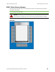
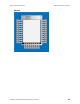
Table Of Contents
- Digi XBee® RR RF Module Hardware Reference Manual
- Safety instructions
- Safety instructions
- Инструкции за безопасност
- Sigurnosne upute
- Bezpečnostní instrukce
- Sikkerhedsinstruktioner
- Veiligheidsinstructies
- Ohutusjuhised
- Turvallisuusohjeet
- Consignes de sécurité
- Sicherheitshinweise
- Οδηγίες ασφαλείας
- Biztonsági utasítások
- Istruzioni di sicurezza
- Drošības instrukcijas
- Saugos instrukcijos
- Sikkerhetsinstruksjoner
- Instrukcje bezpieczeństwa
- Instruções de segurança
- Instructiuni de siguranta
- Bezpečnostné inštrukcie
- Varnostna navodila
- Módulos XBee
- Säkerhets instruktioner
- Specifications
- IEEE 802.15.4-specific specifications
- Mechanical drawings
- Pin signals
- Design notes
- Regulatory information
- XBIB-C development boards
- Manufacturing information

Regulatory information United States (FCC)
Digi XBee® RR RF Module Hardware Reference Manual
51
Host product user guides should include the antenna table if end customers are permitted to select
antennas.
2.4 Limited module procedures
Not applicable.
2.5 Trace antenna designs
While it is possible to build a trace antenna into the host PCB, this requires at least a Class II
permissive change to the FCC grant which includes significant extra testing and cost. If an embedded
trace antenna is desired, simply select the XBee module variant with the preferred antenna.
2.6 RF exposure considerations
For RF exposure considerations see RF exposure and FCC-approved antennas (2.4 GHz).
Host product manufacturers need to provide end-users a copy of the “RF Exposure” section of the
manual: RF exposure.
2.7 Antennas
A list of approved antennas is provided for the XBee RR product. For the XBee RR, see The following
table shows the antennas approved for use with the XBee RR RF Module.. For the XBee-PRO RR, see
XBee RR-PRO RF module.
2.8 Label and compliance information
Host product manufacturers need to follow the sticker guidelines outlined in OEM labeling
requirements.
2.9 Information on test modes and additional testing requirements
Contact a Digi sales representative for information on how to configure test modes for the XBee RR
product.
2.10 Additional testing, Part 15 Subpart B disclaimer
All final host products must be tested to be compliant to FCC Part 15 Subpart B standards. While the
XBee RR unit was tested to be compliant to FCC unintentional radiator standards, FCC Part 15 Subpart
B compliance testing is still required for the final host product. This testing is required for all end
products, and XBee RR Part 15 Subpart B compliance does not affirm the end product’s compliance.
See FCC notices for more details.
Over-voltage detection
Over-voltage detection sends out a modem status of 0x0D indicating that the voltage supply limit has
been exceeded. The device will still operate but limits the RF power level PL setting to a value of 3
when the operating voltage reaches 3.8 volts or higher to meet regulatory RF power requirements.
While the device is in this mode of operation it will be forced into API mode for the over-voltage
modem status to be sent out the serial port every 15 seconds when API mode is set to 1 or 2.