ConnectPort™ X Family User’s Guide ConnectPort™ X Family Products: ConnectPort X2 ConnectPort X2 XTend™/XStream® variants ConnectPort X4 ConnectPort X4 H ConnectPort X8 Note: This guide covers only the ConnectPort X Family products listed above.
©Digi International Inc. 2010. All Rights Reserved. The Digi logo, Digi Connect, iDigi, ConnectPort, Digi SureLink, Digi Dialserv are trademarks or registered trademarks of Digi International, Inc. All other trademarks mentioned in this document are the property of their respective owners. Information in this document is subject to change without notice and does not represent a commitment on the part of Digi International.
Contents Contents Contents ..............................................................................................................................................................................3 About this guide .................................................................................................................................................................7 Purpose ........................................................................................................................
Contents Chapter 2: Hardware ............................................................................................................................................................. 38 Hardware installation for ConnectPort X4 H ...........................................................................................................39 Connector pinouts...........................................................................................................................................
Contents Chapter 4: Monitor and manage Digi devices.................................................................................................................... 182 Monitoring capabilities from iDigi Manager Pro...................................................................................................183 Monitor/manage XBee networks..................................................................................................................
Contents Chapter 7: Troubleshooting................................................................................................................................................. 235 Troubleshooting Resources ....................................................................................................................................235 System status LEDs................................................................................................................................................
About this guide Purpose This guide describes and shows how to install, provision, configure, monitor, and administer Digi devices. Audience This guide is intended for those responsible for setting up Digi devices. It assumes some familiarity with networking concepts and protocols.A glossary is provided with definitions for networking terms and features discussed in the content. Scope This guide focuses on configuration, monitoring, and administration of Digi devices.
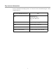
Digi contact information For more information about Digi products, or for customer service and technical support, contact Digi International. To Contact Digi International by: Use: Mail Digi International 11001 Bren Road East Minnetonka, MN 55343 U.S.A. World Wide Web: http://www.digi.com/support/ email http://www.digi.com/support/ Telephone (U.S.
Important Safety Information Introduction C H A P T E R 1 This chapter introduces Digi devices and their product families, types of connections and data paths in which Digi devices can be used, and the interface options available for configuring, monitoring, and administering Digi devices. Important Safety Information To avoid contact with electrical current: Never install electrical wiring during an electrical storm.
ConnectPort X Family products ConnectPort X Family products The ConnectPort X Family of products is intended to provide gateway functionality between various network technologies such as Ethernet, cellular, Wi-Fi, and XBee.
Features Features This is an overview of key features in Digi devices. Software features are covered in more detail in the next three chapters. Hardware specifications and are covered in Chapter 6, "Specifications and certifications" User interfaces There are several user interfaces for configuring and monitoring Digi devices, including the following. iDigi Manager Pro A web-based interface for configuring, monitoring, and administering Digi devices.
Features Quick reference for configuring features This guide primarily focuses on configuring, monitoring, and administering Digi devices from the web interface. This table provides a quick reference for configuring features and performing device tasks, and where to find the features and settings in the web interface and this guide. Click the page number in the Page column to jump to instructions on configuring or using the feature. Some features are configurable from the command line interface only.
Features Feature/task Path to feature in the web interface See page Connection management: Management > Serial Ports 202 Manage Management > Connections > Virtual Private Network (VPN) Settings 202 Manage Management > Connections > Active System Connections 202 Management > Network Services (Currently only DHCP server settings managed from here) 203 Configuration > Network > Advanced Network Settings 97 Configuration > Network > Dynamic DNS Update Settings 72 Dynamic Host Configurati
Features Feature/task Path to feature in the web interface See page IP address settings Configuration > Network > IP Settings Configuration > Network > Advanced Settings 48, 59, 64, 97 IP filtering / access control Configuration > Network > IP Filtering Settings 75 IP forwarding: Network Address Translation (NAT) and port forwarding configuration/static routes Configuration > Network > IP Forwarding Settings 76 IP pass-through Configuration > Network > IP Pass-through 84 Configuration > Mobi
Features Feature/task Path to feature in the web interface See page RealPort (COM port redirection) configuration Configuration > Serial Ports > port > Port Profile Settings > RealPort See also the RealPort Installation Guide.
Features Feature/task Path to feature in the web interface See page Simple Network Management Protocol (SNMP): Configure SNMP through the web interface Configuration > System > Simple Network Management Protocol (SNMP) Settings 153 Enable/disable SNMP service Configuration > Network > Network Services 68 Enable/disable SNMP alarm Configuration > Alarms > alarm > Send SNMP trap to following destination when alarm occu rs 148, 149 Use Basic network and serial settings configurable
Features Feature/task Path to feature in the web interface See page XBee wireless network configuration and management: XBee Configuration > XBee Network 127 XBee In iDigi Manager Pro, the XBee Networks view 51 See also the iDigi User’s Guide XBee Administration > System Information > XBee Network See also the iDigi Manager Pro’s XBee Networks view and detailed view of network nodes.
Features Hardware features A summary of hardware features, including power-supply information, is in "Hardware specifications" on page 223. Network interface features A detailed list of network interface features is in Chapter 6, "Specifications and certifications". See also the data sheet for your Digi product. Configurable network services Access to network services can be enabled and disabled. This means that a device’s use of network services can be restricted to those strictly needed by the device.
Features IP protocol support All Digi devices include a Robust on-board TCP/IP stack with a built-in web server.
Features Serial data communication over TCP and UDP Digi devices support serial data communication over TCP and UDP. Key features include: Serial data communication over TCP, also known as autoconnect and tcpserial can automatically perform the following functions: – Establish bidirectional TCP connections, known as autoconnections, between the serial device and a server or other network device. Autoconnections can be made based on data and or serial hardware signals.
Features Simple Network Management Protocol (SNMP) Simple Network Management Protocol (SNMP) is a protocol for managing and monitoring network devices. SNMP architecture enables a network administrator to manage nodes--servers, workstations, routers, switches, hubs, etc.--on an IP network; manage network performance, find and solve network problems, and plan for network growth. Digi devices support SNMP Versions 1 and 2.
Features Point-to-Point Protocol (PPP) The Point-to-Point Protocol (PPP) transports multi-protocol packets over point-to-point links. PPP encapsulates the data packet, allows the server to inform the dial-up client of its IP address (or client to request the IP address), authenticates the exchange, negotiates multiple protocols, and reassembles the data packet for network communication.
Features Mobile/Cellular features and protocol support Key cellular features in cellular-enabled Digi devices include: GSM: GPRS, EDGE, UMTS, HSPA, SMS CDMA: 1xRTT, Ev-DO (Revs 0 and A) IPSec ESP / IKE IP Pass-through, also known as bridge mode 3-5 Volt SIM card Signal-strength LEDs Provisioning wizard For Digi devices equipped with a Code-Division Multiple Access (CDMA)-based cellular modem, the Mobile Device Provisioning Wizard is available in the web interface to properly configu
Features RealPort software Digi devices use the patented RealPort COM/TTY port redirection for Microsoft Windows. RealPort software provides a virtual connection to serial devices, no matter where they reside on the network. The software is installed directly on the host PC and allows applications to talk to devices across a network as though the devices were directly attached to the host. Actually, the devices are connected to a Digi device somewhere on the network.
Features Security features in Digi devices Secure access and authentication One password, one permission level. Passwords can be issued to device users. Selective enabling/disabling network services such as ADDP, RealPort, Encrypted RealPort, HTTP/HTTPS, LPD, Remote Login, Remote Shell, SNMP, and Telnet. Can control access to inbound ports. Can control access to specific devices, IP addresses, or networks through IP filtering.
Features SNMP security SNMP “set” commands can be disabled to make use of SNMP read-only. Changing public and private community names is recommended to prevent unauthorized access to the device. Network Port Scan Cloaking The Network Port Scan Cloaking feature allows you to configure this Digi device to ignore (discard) received packets for services that are hidden or not enabled and network ports that are not open.
Supported connections and data paths in Digi devices Supported connections and data paths in Digi devices Digi devices allow for several kinds of connections and paths for data flow between the Digi device and other entities. These connections can be grouped into two main categories: Network services, in which a remote entity initiates a connection to a Digi device. Network/serial clients, in which a Digi device initiates a network connection or opens a serial port for communication.
Supported connections and data paths in Digi devices Network services associated with serial ports in general RealPort: A single TCP connection manages (potentially) multiple serial ports. Modem emulation, also known as pseudo-modem (pool): A TCP connection to the “pool” port is interpreted as an incoming call to an available pseudo-modem in the “pool” of available port numbers.
Supported connections and data paths in Digi devices Network/serial clients A network/serial client connection is one in which a Digi device initiates a network connection or opens a serial port for communication.
Interfaces for configuring, monitoring, and administering Digi devices Interfaces for configuring, monitoring, and administering Digi devices There are several interfaces for configuring, monitoring, and administering Digi devices. These interfaces are covered in more detail later in this guide.
Interfaces for configuring, monitoring, and administering Digi devices Digi Device Discovery utility The Digi Device Discovery utility locates Digi devices on a network and allows for opening the web interface for discovered devices, configuring network settings, and rebooting the device.
Interfaces for configuring, monitoring, and administering Digi devices iDigi™ Manager Pro interface iDigi Manager Pro is an optional, centralized device and network management package.
Interfaces for configuring, monitoring, and administering Digi devices Web interface A web interface is provided as an easy way to configure and monitor Digi devices. Configurable features are grouped into several categories. These categories vary by product; examples include Network, Serial Port, Alarms, and System. Most of the configurable features are arranged by most basic settings on a page, with associated and advanced settings accessible from that page.
Interfaces for configuring, monitoring, and administering Digi devices Command-line interface Digi devices can be configured by issuing commands from the command line. The command-line interface allows communication directly without a graphical interface. To access the command line from the Digi Device Discovery utility, click Telnet to command line. For example, here is a command issued from the command line to assign the IP address to the Ethernet interface: #> set network ip=192.168.1.
Interfaces for configuring, monitoring, and administering Digi devices Simple Network Management Protocol (SNMP) Simple Network Management Protocol (SNMP) is a protocol for managing and monitoring network devices. The SNMP architecture enables a network administrator to manage nodes-servers, workstations, routers, switches, hubs, etc.--on an IP network; manage network performance, find and solve network problems, and plan for network growth. Digi devices support SNMP Versions 1 and 2.
Interfaces for configuring, monitoring, and administering Digi devices Monitoring capabilities and interfaces Monitoring Digi devices includes such tasks as checking device status, checking runtime state, viewing serial port operations, and reviewing network statistics, and managing their connections. There are several interfaces for monitoring Digi devices and managing their connections.
Interfaces for configuring, monitoring, and administering Digi devices Device administration Periodically, administrative tasks need to be performed on Digi devices, such as uploading and managing files, changing the password for logging onto the device, backing up and restoring device configurations, updating firmware, restoring the configuration to factory defaults, and rebooting.
Hardware Hardware C H A P T E R 2 This section details requirements and recommendations for installing ConnectPort X Family product hardware. See also "Specifications and certifications" on page 222 and "System status LEDs" on page 236.
Hardware Hardware installation for ConnectPort X4 H Connector pinouts The ConnectPort X4 H has three connectors. The 2-pin power connector is properly wired before shipping. The 9-pin RS-232, RS-422, and RS-485 connector must be wired by the customer according to the wiring diagram and pinout table. The 14-pin input/output connector must also be wired by the customer according to the wiring diagram and pinout table.
Hardware 9-pin RS-232, RS-422, and RS-485 connector pinouts RS-232 Pin RS-422 Function Pin RS-485 Function Pin Function 1 CD 1 CTS(-) 1 CTS(-) 2 RXD 2 RXD(+) 2 485(+) 3 TXD 3 TXD(+) 3 N/A 4 DTR 4 RTS(-) 4 RTS(-) 5 GND 5 GND 5 GND 6 DSR 6 RXD(-) 6 485(-) 7 RTS 7 RTS(+) 7 RTS(+) 8 CTS 8 CTS(+) 8 CTS(+) 9 RI 9 TXD(-) 9 N/A 9 +12VDC switched power out 9 +12VDC switched power out 9 +12VDC switched power out 40
Hardware 14-pin input/output connector Pin Function 1 +24VDC sensor power 2 GND 3 Input/Output 1 4 +24VDC sensor power 5 GND 6 Input/Output 2 7 +24VDC sensor power 8 GND 9 Input/Output 3 10 +24VDC sensor power 11 GND 12 Input/Output 4 13 +24VDC for auxiliary power 14 GND for auxiliary power 41
Hardware Cable fittings To route serial, Ethernet or sensor cables outside the enclosure, and maintain IP66 rating, the three hole plugs can be replaced with cable glands, available in different diameters. These cable glands can be purchased separately from Digi. To wire sensors through cable glands: 1 Locate cord glands. 2 Wire sensor to the 14-pin connector plug using the pinout guide provided in the enclosure or in the pinout section on page 39. Up to 4 sensors can be wired into the 14-pin connector.
Hardware Antenna options and connectors ConnectPort X4 H has two antenna connectors, one for cellular networks and the other for XBee networks. Connect the antennas that come with the unit you purchased.
Hardware SIM card slots There are two SIM card slots on the circuit board.If you are only using one SIM, insert it into the primary SIM slot (lower slot).
Hardware Power cable fitting Class 1, Div 2 units Warning Do not plug in or apply power to the unit until all connections are made to the unit in the following steps. For customers who have purchased a C1D2-approved unit with cable and conduit to wire into the main power supply: 1 Make sure that the mains power to the junction box where the cable is to be wired into is off.
Hardware Optional Ethernet hub feature The Ethernet hub for the ConnectPort X4 H is pre-wired to pins 13 and 14 of the 14-pin Phoenix sensor connector for power and ground. It also comes with an Ethernet cable connecting one of the five Ethernet ports to the Ethernet connector in the main board (any port can be used). The remaining four ports can be used as desired. .
Configure Digi devices C H A P T E R 3 This chapter describes how to configure a Digi device.
Default IP address and methods for assigning an IP address Default IP address and methods for assigning an IP address All products that have a cellular (WAN) interface ship with static IP address for the Ethernet port of 192.168.1.1 and DHCP server enabled by default. Therefore, simply connecting a laptop computer to the Ethernet port of these products allows direct access to the web interface for configuration.
Default IP address and methods for assigning an IP address Configure an IP address using DHCP An IP address can also be configured using Dynamic Host Configuration Protocol (DHCP). DHCP is an Internet protocol for automating the configuration of computers that use TCP/IP. DHCP can be used to automatically assign IP addresses and deliver TCP/IP stack configuration parameters. As mentioned previously, all products that have a cellular (WAN) interface ship with static IP address for the Ethernet port of 192.
Default IP address and methods for assigning an IP address IP addresses and iDigi Manager Pro From the iDigi Manager Pro interface, the Ethernet/LAN address for a Digi device can be changed only; an address cannot be assigned. The mobile/cellular device is typically provided by the mobile service provider; check with your mobile service provider on how they handle addresses.
Configuration through iDigi Manager Pro Configuration through iDigi Manager Pro iDigi Manager Pro is an on-demand service. After creating an iDigi account, you can connect to iDigi Manager Pro. There are no infrastructure requirements. Remote devices and enterprise business applications connect to iDigi Manager Pro via standards-based Web Services. For details on using iDigi as a management interface, creating an account on iDigi.com and add your ConnectPort X Family device to the iDigi.
Configuration through the web interface Configuration through the web interface Open the web interface To open the web interface, either enter the Digi device’s URL in a web browser and log on to the device, if required, or use the Digi Device Discovery utility to locate it and open its web interface. By entering the Digi device’s IP address in a web browser 1 In the URL address bar of a web browser, enter the IP address of the device.
Configuration through the web interface Discover devices From the start menu, select Start > Programs > Digi Connect > Digi Device Discovery. The Digi Device Discovery application is displayed. Locate the device in the list of devices, and double-click it, or select the Digi device from the list and select Open web interface in the Device Tasks list.
Configuration through the web interface Organization of the web interface Here is a home page for a ConnectPort X Family product. The Home page When the web interface is opened, the Home page is displayed. The left side of the Home page has a menu of choices that display pages for configuration, management, and administration tasks, and to log out of the web interface. This chapter focuses on the choices under Configuration and Applications.
Configuration through the web interface Configuration pages The choices under Configuration in the menu display pages for configuring settings for various features, such as network settings, and serial port settings. Some of the configuration settings are organized on sets of linked screens. For example, the Network Configuration screen initially displays the IP Settings, and provides links to Network Services Settings, Advanced Settings, and other network settings appropriate to the Digi device.
Configuration through the web interface Change the IP address from the web interface, as needed Normally, IP addresses are assigned to Digi devices either through DHCP or the Digi Device Setup Wizard. This procedure assumes that the Digi device already has an IP address and you simply want to change it. 1 Open a web browser and enter the Digi device’s current IP address in the URL address bar. 2 If security is enabled for the Digi device, a login prompt is displayed.
Configuration through the web interface Network configuration settings The Network configuration pages include: Ethernet IP settings: For viewing IP address settings and changing as needed. See page 59. WiFi IP settings: For setting the IP address used for wireless LAN communication. See page 60. WiFi LAN settings: For setting basic options for wireless LAN devices such as network name and network connection options. See page 60.
Configuration through the web interface Host List settings: Adds or removes entries from the host list. For DialServ, the host list provides a means to map a phone number (in the local name field) to a network destination, (in the “resolves_to” field). See page 95. Virtual Router Redundancy Protocol (VRRP) settings: For configuring a number of routers to represent a virtual router, which simplifies configuration of hosts on a network.
Configuration through the web interface Ethernet IP settings The Ethernet IP Settings page configure how the IP address of the Digi device is obtained, either by DHCP or by using a static IP address, subnet mask, and default gateway. For more information about how these settings are assigned and used in your organization, contact your network administrator. Obtain an IP address automatically using DHCP: When the Digi device is rebooted, it will obtain new network settings.
Configuration through the web interface WiFi IP settings The WiFi IP settings configure how the IP address of a Wi-Fi-enabled Digi device is obtained. It has the same settings as the Ethernet IP settings page. WiFi LAN settings Digi devices with Wi-Fi (wireless LAN) capability contain a wireless network interface that may be used to communicate to wireless networks using 802.11b8 technology.
Configuration through the web interface WiFi security settings The WiFi security settings specify the wireless security settings that the wireless network uses. Multiple security and authentication modes may be chosen depending on the configuration of the access point or wireless network. The wireless device will automatically select and determine the authentication and encryption methods to use while associating to the wireless network.
Configuration through the web interface Data Encryption: Multiple encryption methods can be selected. – Use any available encryption method: enables all of the methods. The actual method used will be determined by the capabilities of the wireless network. – Use the following selected method(s): Selects one or more encryption methods. Open System: No encryption is used over the wireless link. Open System encryption is valid only with Open System and Shared Key authentication.
Configuration through the web interface WiFi 802.1x authentication settings These settings are not required based on the current Wi-Fi authentication settings. They are only configurable when WEP with 802.1x authentication or WPA with 802.1x authentication are enabled on the WiFi Security Settings tab. EAP Methods: These are the types of Extensible Authentication Protocols (EAP) or outer protocols that are allowed to establish the initial connection with an authentication server or access point.
Configuration through the web interface DHCP server settings The DHCP server feature can be enabled in a Digi device to allow other devices or hosts on this network to be assigned dynamic IP addresses. This DHCP server supports a single subnetwork scope. For the DHCP server to operate, the Digi device must be configured to use a static IP address. For information on how to configure static IP settings, see "Ethernet IP settings" on page 59.
Configuration through the web interface grace period When a DHCP client actively releases a lease, or when the lease expires without being renewed by the client, the DHCP server does not immediately delete the lease record and return the associated IP address to the available address pool.
Configuration through the web interface DHCP server configuration settings Here are the configuration settings for the DHCP server. Typically, these settings can be modified without having to restart the DHCP server for the changes to become effective in the running server. Enable Dynamic Host Configuration Protocol (DHCP) Server: Enables the DHCP server feature on this Digi device. Note that for the DHCP server to operate, the Digi device must be configured to use a static IP address.
Configuration through the web interface Send the DHCP Server IP address as a DNS Proxy Server: This option configures the DHCP Server to send its IP address to a DHCP client as the first DNS server in its lease information. This Digi device supports a DNS Proxy feature that will relay DNS requests and responses between DNS clients and servers. The DNS Proxy is not a feature of the DHCP Server itself, but rather it is managed elsewhere in the configuration settings for this Digi device.
Configuration through the web interface Network services settings The Network Services page shows a set of common network services that are available for Digi devices, and the network port on which the service is running. Common network services can be enabled and disabled, and the TCP port on which the network service listens can be configured. Disabling services may be done for security purposes. That is, certain services can be disabled so the device runs only those services specifically needed.
Configuration through the web interface The table shows network services, services provided, and the default network port number for each service. Service Services provided Device Discovery, also known as Advanced Digi Discovery Protocol (ADDP) Discovery of Digi devices on a network. Disabling this service disables use of the Digi Device Discovery utility to locate the device, either on its own or as part of running the Digi Device Setup Wizard.
Configuration through the web interface Service Services provided Default network port number Simple Network Management Protocol (SNMP) Managing and monitoring the Digi device. To run SNMP in a more secure manner, note that SNMP allows for “sets” to be disabled.This securing is done in SNMP itself, not through this command. If disabled, SNMP services such as traps and device information are not used.
Configuration through the web interface Network services and IP pass-through The IP pass-through feature (Configuration > Network > IP Pass-through) causes the Digi device to be bridged transparently between the Ethernet and mobile data links. Enabling IP Passthrough disables many device features, including many network services.
Configuration through the web interface Dynamic DNS update settings A Dynamic DNS (DDNS) service allows a user whose IP address is dynamically assigned to be located by a host or domain name. Before a DDNS service may be used, you must create an account with the DDNS service provider. The provider will give you account information such as username and password. You will use this account information to register your IP address and update it as it changes.
Configuration through the web interface DynDNS.org DDNS Service: You must create your account at DynDNS.org before you can successfully register the IP address of your Digi device with their service. Please familiarize yourself with their service options and requirements, in order to most effectively use this feature of your Digi device. This DDNS service supports only public IP addresses. If you have a private IP address (such as 192.168.x.x or 10.x.x.x), your update requests will be rejected.
Configuration through the web interface Status and history information The next settings show status and history information for the DDNS service. Most Recent DDNS Service Update Status: This section provides the status of the most recent attempt to update a DDNS service or server. The displayed information confirms the success of an update request, or it may offer information as to the reason an update request was rejected by the service or server. A number of status items are shown.
Configuration through the web interface IP filtering settings You can better restrict your device on the network by only allowing certain devices or networks to connect. This is better known as IP Filtering or Access Control Lists (ACL). By enabling IP filtering, you are telling the device to only accept connections from specific and known IP addresses or networks.
Configuration through the web interface IP forwarding settings When a Digi device acts as a router and communicates on both a private and public network with different interfaces, it is sometimes necessary to forward certain connections to other devices. This is also known as Network Address Translation (NAT) or Port Forwarding. When an incoming connection is made to the device on the private network, the IP port is searched for in the table of port forwarding entries.
Configuration through the web interface – Enable DMZ Forwarding to this IP address: DMZ Forwarding allows you to specify a single host (DMZ Server) on the private (internal) network that is available to anyone with access to the NAT Public Interface IP address, for any TCP- and UDP-based services that haven't been configured. Services enabled directly on the Digi device take precedence over (are not overridden by) DMZ Forwarding.
Configuration through the web interface – Forward TCP/UDP/FTP connections from external networks to the following internal devices: Specifies a list of connections based on a specific IP port and where those connections should be forwarded to. Typically the connecting devices come from the public side of the network and are redirected to a device on the private side of the network. It is possible to forward a single port or a range of ports.
Configuration through the web interface IP Network Failover settings The IP Network Failover feature provides a dynamic method for selecting and configuring the default gateway for the Digi device. Failover uses of a set of rules and link tests to determine whether a particular network interface can be used to communicate with a specified destination. The user configures these rules, link tests and the priority order of the interfaces.
Configuration through the web interface Network Failover General Settings Enable IP Network Failover: Enable the Network Failover feature in the Digi device. Click the checkbox to turn failover on or off. Enable fallback to the non-failover default gateway priority method: The fallback option is used if a default gateway cannot be configured by Network Failover.
Configuration through the web interface Send Interval (Ping Test): The time interval in seconds between sending ping requests during a ping link test. The ping tests sends a ping request. If no ping reply is received before the Send Interval expires, another ping request is sent. – TCP Connection Test: Click on the radio button to select the TCP Connection Test as the link test to use for this interface.
Configuration through the web interface The following four Link Test options are used if the Ping or TCP Connection Link Test is selected. Repeat the test every: N seconds: The time interval (N) in seconds between the end of a successful link test and the start of the next link test for the network interface. This interval is used only after a successful test. Shorter intervals verify the link more often, but they also increase the packet traffic over the network interface being tested.
Configuration through the web interface Socket tunnel settings A Socket Tunnel can be used to connect two network devices: one on the Digi device’s local network and the other on the remote network. This is especially useful for providing SSL data protection when the local devices do not support the SSL protocol. One of the endpoint devices is configured to initiate the socket tunnel. The tunnel is initiated when that device opens a TCP socket to the Digi device device on the configured port number.
Configuration through the web interface Virtual Private Network (VPN) settings Virtual Private Networks (VPNs) are used to securely connect two private networks together so that devices may connect from one network to the other network using secure channels.VPN uses IP Security (IPSec) technology to protect the transferring of data over the Internet. All Digi Cellular Family products except Digi Connect WAN support VPNs. The Digi device is responsible for handling the routing between networks.
Configuration through the web interface VPN Global Settings General Security Settings – Enable Antireplay: Antireplay allows the IPsec tunnel receiver to detect and reject packets that have been replayed. Set this field to match that at the remote VPN gateway. The default is Enabled. Important: Disable Antireplay if you use manual keyed tunnels. Miscellaneous Settings – Suppress SA lifetime during IKE Phase 1: In most cases, leave this option unchecked.
Configuration through the web interface VPN tunnel configuration settings Description: Enter a short, one-line description of the VPN tunnel. VPN Tunnel: Displays settings for encryption and authentication keys. Selecting ISAKMP is recommended; it is the standard protocol used by almost all VPN devices.
Configuration through the web interface Local Endpoint: If the Local Endpoint Type is set to Local endpoint is an internal interface, the following prompts are displayed: – Host address for tunnel's internal VPN interface: In the IP Address field, enter the IP address for the virtual network interface in the IP Address. This is the IP address which will be visible to devices on the remote private network.
Configuration through the web interface ISAKMP Phase 1 Settings – General Security Settings for Phase 1 Connection Mode: Main|Aggressive: Set the connection mode to match that configured on the remote VPN device. If aggressive mode is selected, then the VPN device will try aggressive mode first, and then try main mode if aggressive mode fails. Enable Perfect Forward Secrecy (PFS): Set this option to enable PFS.
Configuration through the web interface – ISAKMP Phase 2 Settings: The SAs used for bulk data transfer are created during phase 2. The phase 2 settings you specify will determine the level of security used when devices on the local private network communicate with devices on the remote private network. As with the other settings, the both the Digi unit and the remote VPN device must be configured to use the same values.
Configuration through the web interface Example VPN configuration The diagram shows a Digi Connect WAN VPN used as a primary remote site router: HQ 172.16 .5.0/2 4 Remote Site IPSec ESP Private IP Tunnel 172.17.1.0/24 Digi Connect WAN VPN Cellular Data Network 166.123.99.99 VPN Appliance P WR WIC 0 CT C A / H0 WIC 0 AT C /C H 0 ET H AC T OK CT C A / H1 C T /C H 1 A COL Internet 172.16.5.1 209.123.123.123 172.17.1.
Configuration through the web interface Requirements for VPN tunnels To establish an IPSec VPN tunnel, the IP address of the mobile interface must be publicly accessible. The IP address can be either static or dynamic depending upon the requirements of your VPN end point. However, the IP address cannot be within a private range of addresses (for example, 10.0.0.0, 172.16.0.0 or 192.168.0.0).
Configuration through the web interface IP pass-through settings There are many application scenarios where a router is used to decide upon alternative routes using a primary and a secondary (or backup) interface. In many of these configurations, the router is required to use a public IP address as assigned by the network over which it is communicating.
Configuration through the web interface If the third-party router’s WAN interface is attached to the Digi device’s Ethernet port, and the Digi device’s mobile interface receives the IP address 166.213.2.215, the router’s WAN port is assigned the same IP address 166.213.2.215. If the router is receiving the IP address dynamically; the DNS server addresses, subnet mask, and default gateway information will be filled in automatically.
Configuration through the web interface Using pinholes to manage the Digi device IP pass-through uses a concept called pinholes. A Digi device can be configured to listen on specific TCP ports, and terminate those connections at the Digi device for purposes of managing it. Those ports are called pinholes, and they are not passed on to the device connected to the Ethernet port of the Digi device.
Configuration through the web interface Host List settings The Host List settings page is used to add or remove entries from the host list. For Digi devices using the DialServ feature, the host list provides a means to map a phone number to a network destination. The Host List settings are: Local Name: A phone number Resolves To: a network destination).
Configuration through the web interface Virtual Router Redundancy Protocol (VRRP) settings Virtual Router Redundancy Protocol (VRRP) is a redundancy protocol for routers. VRRP allows several routers on a subnet to use the same virtual IP address, with the physical routers representing a “virtual router.” Two or more physical routers are configured to stand for the virtual router, with only one doing the actual routing at any given time.
Configuration through the web interface Advanced network settings The Advanced Network Settings are used to further define the network interface. These settings rarely need to be changed. Contact your network administrator for more information about these settings. IP Settings These settings are used to fine-tune IP address settings. Host Name: The host name to be placed in the DHCP Option 12 field. This is an optional setting which is only used when DHCP is enabled.
Configuration through the web interface Gateway Priority: List of network interfaces in priority order used to determine the default gateway. The default gateway is used to route IP packets to an outside network, unless controlled by another route. A network interface may have a static gateway configured, or obtain a gateway from DHCP or other means when it is connected. The first interface in this list that supplies a gateway will be used as the default gateway.
Configuration through the web interface DNS Proxy Settings Enable DNS Proxy Service: Enables the DNS Proxy feature on this Digi device. DNS Proxy permits DNS client hosts to communicate with this Digi device as if it were a DNS Server. It forwards the DNS client's request to one of the DNS servers configured in its network settings. The response from the actual DNS server will be relayed to the requesting client when it is received by the DNS Proxy.
Configuration through the web interface Request Idle Time-To-Live: Specifies the period of time, in seconds, that a DNS client request will remain in the DNS Proxy cache, before it is deleted. This is a period of idle time, during which neither a DNS client request retry is received by the DNS Proxy, nor a DNS server response is received by the DNS Proxy, for a specific DNS client request.
Configuration through the web interface Network Port Scan Cloaking The Network Port Scan Cloaking feature allows you to configure this Digi device to ignore (discard) received packets for services that are hidden or not enabled and network ports that are not open. Malicious software on the Internet may scan IP addresses, protocols and ports to try to gain access to hosts.
Configuration through the web interface Ethernet Interface Speed: The Ethernet speed the Digi device uses on the Ethernet network. – 10: The device operates at 10 megabits per second (Mbps) only. – 100: The device operates at 100 Mbps only. – auto: The device senses the Ethernet speed of the network and adjusts automatically. The default is auto. If one side of the Ethernet connection is using auto (negotiating), the other side can set the Ethernet speed to whatever value is desired.
Configuration through the web interface Mobile (cellular) settings The Mobile Settings pages configure how to connect to mobile (cellular) networks using the mobile connection, including the service provider, service plan, and connection settings used in connecting to the mobile network. If your Digi device has not already been provisioned for use in the mobile network, you can launch a wizard to provision it from these pages.
Configuration through the web interface Set mobile configuration settings to factory defaults The Set to Defaults button on the Mobile Configuration page sets all the mobile settings to factory defaults and sets the Service Provider selection back to deselected. Mobile service provider settings The Mobile Service Provider settings part of the screen identifies the service provider to use in connecting to the mobile network.
Configuration through the web interface Provision a mobile device Mobile device provisioning is needed to properly configure the Digi device with the required configuration used to access the mobile network. The device must be provisioned before you will be able to create a data connection to the mobile network.The device only needs to be provisioned once. This type of provisioning applies only to Digi devices that have a CDMA cellular module.
Configuration through the web interface Automatic versus manual provisioning There are different types of provisioning methods depending upon your mobile provider. The Mobile Device Provisioning Wizard will provide the appropriate choices based on the mobile provider selected. Two main provisioning methods are: Automatic Provisioning: Typically, an automatic provisioning process called IOTA (IPBased Over the Air) is used to provision the device.
Configuration through the web interface 1 Select a mobile service provider from the list. 2 Select automatic or manual provisioning. The main difference between automatic and manual provisioning is that manual provisioning involves entering more information. You will have received all of this information from your mobile service provider during account setup. 3 As needed, enter device provisioning information provided by your mobile service provider.
Configuration through the web interface 4 Device provisioning in progress... 5 Provisioning complete. Upon successful completion of provisioning, a screen is displayed stating that the provisioning was successful.Click Finish. If provisioning fails: The first screen of the provisioning wizard is displayed again. Instead, you must perform manual provisioning. 6 Click Apply on the Mobile Configuration page to complete the provisioning.
Configuration through the web interface Mobile connection settings Mobile connection settings configure how the mobile connection is established and maintained. Re-establish connection when no data is received for a period of time: Inactivity timeout: Whether the mobile connection will be disconnected and reestablished after no data has been received over the link for the specified amount of time, in seconds.
Configuration through the web interface Mobile Carrier Settings Mobile carrier selection allows the mobile device to be configured to use a specific mobile service only. The recommended and normal operation is for the mobile device to automatically find service with an available carrier. However, a manual selection can be configured to force the use of a particular carrier.
Configuration through the web interface Digi SureLink™ settings The Mobile Connection Settings configure Digi SureLink™ settings for a Digi device. SureLink ensures that a Digi device is in a state where it can connect to the mobile network, and they can be used to monitor the integrity of the established mobile connection.
Configuration through the web interface Link integrity monitoring settings Enable Link Integrity Monitoring using the test method selected below: Enables or disables the link integrity monitoring tests. If this setting is enabled, the other Link Integrity Monitoring settings may be configured and are used to verify the functional integrity of the mobile connection. The default is off (disabled).
Configuration through the web interface TCP Connection Test: Enables or disables the creation of a new TCP connection as a test to verify the integrity of the mobile connection. The test is successful if a TCP connection is established to a specified remote host and port number. If the remote host actively refuses the connection request, the test is also considered to be successful, since that demonstrates successful two-way communication over the mobile connection.
Configuration through the web interface Test only when idle: if no data is received for the above period of time: Specifies that the test repeat interval (above) is to be used as an idle period interval. That is, initiate the selected link integrity test only after no data has been received for the specified interval of time. This changes the behavior of the test in that the test interval varies according to the presence of other data received from the mobile connection.
Configuration through the web interface Update PRL settings Note These settings apply to Digi cellular-enabled products that use the Sierra Wireless MC57xx series CDMA/EVDO modules. The Update PRL page is for loading a preferred roaming list (PRL) into the cellular module on the Digi device. A PRL is a database that resides in a mobile device that contains information used during the system selection and acquisition process.
Configuration through the web interface Short Message Service (SMS) settings The following options configure the cellular Short Message Service (SMS) capabilities of the mobile module of the Digi device. Important Notes: Currently, SMS is supported for Digi devices with GSM cellular modems only. To determine whether the cellular modem in a Digi device supports SMS, Telnet to the command line and enter the show smscell command.
Configuration through the web interface Default Message Receiver: When a message is received via SMS, the Default Message Receiver is used to determine which SMS “user” will receive the message and process it. This handling pertains to messages that are not enabled commands for which command processing is performed. The choices for this option are: – Log Only: The received message is logged but otherwise not processed (default option).
Configuration through the web interface Built-In Command Settings Several built-in commands are supported for execution via SMS messages sent to your Digi device. Descriptions of built-in command-related settings for the SMS feature follow. Full detailed descriptions of the SMS command syntax and supported command options is available on the Digi support web site. Supported commands The following commands are supported.
Configuration through the web interface Sender Control List (SCL) Settings The Sender Control List (SCL) permits the user to select the addresses (or phone numbers) from which SMS messages will be accepted. This is in effect a “Caller ID” capability in which message senders are screened by the Digi device and either processed or discarded according to the configured SCL rules. Following are descriptions of the SCL-related settings for the SMS feature.
Configuration through the web interface Supported Character Set For SMS via GSM service, it is necessary to translate between the GSM 03.38 7-bit alphabet and ASCII, which is the native character set for the Digi device and is the character set used in the CLI and web UI. The characters of ASCII and GSM 03.38 do not map one-to-one, and in fact some ASCII characters must be represented in GSM 03.38 as multi-character escape sequences (per extensions to the original GSM 03.38 alphabet).
Configuration through the web interface Supported character set ASCII Code GSM 03.
Configuration through the web interface Supported character set (Continued) ASCII Code GSM 03.
Configuration through the web interface Supported character set (Continued) ASCII Code GSM 03.38 Code ASCII Character Description 0x29 0x29 ) RIGHT PARENTHESIS 0x2A 0x2A * ASTERISK 0x2B 0x2B + PLUS SIGN 0x2C 0x2C , COMMA 0x2D 0x2D - HYPHEN-MINUS 0x2E 0x2E .
Configuration through the web interface Supported character set (Continued) ASCII Code GSM 03.
Configuration through the web interface Supported character set (Continued) ASCII Code GSM 03.
Configuration through the web interface Supported character set (Continued) ASCII Code GSM 03.
Configuration through the web interface XBee network settings A Digi ConnectPort X gateway provides a gateway between an Internet Protocol (IP) network and a network of various wireless devices containing XBee RF modules. Typically, these XBee devices are small sensors and controllers.
Configuration through the web interface XBee 802.15.4 series products show the XBee module in the gateway as the coordinator, and any XBee Drop-in Networking Accessories as end nodes. Clicking on the Network Address or Extended Address of a node displays the XBee Network Configuration settings for the XBee RF module in the ConnectPort X gateway. The configuration settings include basic and advanced settings for the XBee radio module.
Configuration through the web interface Basic and Advanced radio settings The Basic radio settings control basic operation of the XBee module in an XBee network. Advanced radio settings control behavior of the XBee module at a more detailed level. Generally, these settings can be left at their defaults. For complete settings and descriptions of these options, refer to the Product Manual for the XBee or XBee-PRO RF module in your product. View and change configuration settings as needed.
Configuration through the web interface XBee firmware file-naming conventions The file-naming convention for numbering XBee firmware versions is HW_XYZZ.EXT where: HW = module hardware and network type; that is, the XBee RF protocol running on the module X = a number specifying the network type XYZZ is the full version number in hexadecimal.
Configuration through the web interface X values-Network type Network type X value XBee 802.15.
Configuration through the web interface XBee ZB and Smart Energy standard networks have all node types. Other network types have standard nodes and adapters. ZigBee nodes use different firmware for AT and API mode. Standard nodes support both AT and API modes. The gateway XBee module must be ZigBee type 1 or 3, or non-ZigBee type 0. Remote nodes may be any node type.
Configuration through the web interface XBee firmware versions supported in ConnectPort X gateways Currently, ConnectPort X gateways support these XBee firmware versions: XBee module model type in gateway Supported firmware versions XBee ZB Version 2x21 or greater XBee 802.15.4 Version 1080 or greater XBee DigiMesh 900 MHz Any firmware version XBee DigiMesh 2.
Configuration through the web interface Settings preserved during firmware updates If the gateway is enabled, most XBee module settings will be preserved during the firmware update. Some settings, such as encryption keys, may not be preserved and must be entered again. Note The gateway can be disabled by the set xbee state=off command. It will also be disabled if it cannot communicate with its XBee module. The most likely cause of this state is unsupported firmware on the XBee module.
Configuration through the web interface Firmware Update Status page This page lists all nodes on the XBee network, along with their current firmware update status. Select one or more nodes to be updated by checking the box to the left of the nodes. To select a range of nodes, click on the starting check box, then hold down the Shift key and click on the ending check box. Click on a value in the table to select all nodes with that value.
Configuration through the web interface Update XBee firmware via the web interface--all other ConnectPort X gateways For ConnectPort X gateways that have any other XBee module type than ZB, the process for updating firmware is as follows: 1 In the web interface, go to Configuration > XBee Network > XBee Configuration. On the XBee Configuration page. click the Firmware Update link. The Firmware Update page shows the type of XBee radio in the gateway and the current firmware level.
Configuration through the web interface Serial port settings Use the Serial Port Configuration page to establish a port profile for the serial port of the Digi device. The Serial Port Configuration page includes the currently selected port profile for the serial port, detailed configuration settings for the serial port, dependent on the port profile selected, and links to basic and advanced serial settings.
Configuration through the web interface RealPort profile The RealPort profile maps a COM or TTY port to a serial port. This profile configures a Digi device to create a virtual COM port on a PC, known as COM Port Redirection. The PC applications send data to this virtual COM port and RealPort sends the data across the network to the Digi device. Data is routed to the serial device connected to the Digi device’s serial port. The network is transparent to both the application and the serial device.
Configuration through the web interface TCP Sockets profile The TCP Sockets profile allows serial devices to communicate over a TCP network. The TCP Server allows other network devices to initiate a TCP connection to the serial device attached to the serial port of the Digi device. Automatic TCP connections (autoconnection) The TCP Client allows the Digi device to automatically establish a TCP connection to an application or a network, known as autoconnection.
Configuration through the web interface The application or Digi device that initiates communication must use these network ports numbers. If they cannot be configured to use these network port numbers, change the network port on the Digi device. UDP Sockets profile The UDP Sockets profile allows serial devices to communicate using UDP. The UDP Server configuration allows the serial port to receive data from one or more systems or devices on the network.
Configuration through the web interface Modem Emulation profile The Modem Emulation profile allows a Digi device to sends and receive modem responses to the serial device over the Ethernet instead of PSTN (Public Switched Telephone Network). This profile allows maintaining the current software application but using it over a less-expensive Ethernet network. The commands that can be issued in a modem-emulation configuration are described in the Digi Connect Family Command Reference.
Configuration through the web interface Basic serial settings After selecting a port profile, the profile settings are displayed. Choose the appropriate features for your environment. Here are brief descriptions of the fields in the Basic Serial Settings; see the online help for detailed information about each setting. The Description field specifies an optional character string for the port which can be used to identify the device connected to the port.
Configuration through the web interface TCP settings The TCP Settings are displayed only when the current serial port is configured with the TCP Sockets or the Custom Profile. The settings are as follows: Send Socket ID: Include an optional identifier string with the data sent over the network. The Socket ID can be 1 to 256 ASCII characters.
Configuration through the web interface Close connection after the following number of idle seconds: Enable to close an idle connection. Use the Timeout field to enter the number of seconds that the connection will be idle before it is closed. This can be 1 to 65000 seconds. Close connection when DCD goes low: When selected, the connection will be closed when the DCD (Data Carrier Detected) signal goes low.
Configuration through the web interface Camera settings ConnectPort X Family products support connecting a WatchPort® Camera to one of its USB host ports. One Digi WatchPort V2 USB camera is supported. Camera settings These settings configure the camera operation and handling of images captured by the camera. Enable Camera: Enables and disables camera. When disabled, all camera activity stops and all used memory is freed. Resolution: The resolution level for images.
Configuration through the web interface Alarms The Alarms page is for configuring device alarms and displaying alarm settings. Device alarms are used to send email messages or SNMP traps when certain device events occur. These events include certain data patterns being detected in the data stream, alarms for signal strength and amount of cellular traffic for a given period of time.
Configuration through the web interface Alarm conditions The Alarm Conditions part of the Alarms page shows a list of all of the alarms. Up to 32 alarms can be configured for a Digi device, and they can be enabled and disabled individually. Alarm list and status The alarm list displays the current status of each alarm. This list can be used to list to view alarm status at a glance, then view more details for each alarm as needed.
Configuration through the web interface Alarm configuration To configure an alarm, click on it. The configuration page for individual alarms has two sections. Alarm conditions For specifying the conditions on which the alarm is based, serial data pattern matching, signal strength (RSSI), or data usage. Alarm conditions include: Send alarms based on serial data pattern matching: Click this radio button to specify that this alarm is sent when the specified serial data pattern is detected.
Configuration through the web interface Alarm destinations The Alarm Destination part of the page defines how alarm notifications are sent, either as an email message or an SNMP trap, or both, and where the alarm notification is sent. Send E-mail to the following recipients when alarm occurs: Select the checkbox to specify that the alarm should be sent as an email message. Then specify the following information: – To: The email address to which this alarm notification email message will be sent.
Configuration through the web interface System settings The System Configuration page configures device identity and description information, date and time settings, and settings for Simple Network Management Protocol (SNMP). Device identity settings The device identity settings create a description of the Digi device’s name, contact, and location. This information can be useful for identifying a specific Digi device when working with a large number of devices in multiple locations.
Configuration through the web interface Date and Time settings The Date and Time settings set the Coordinated Universal Time (UTC) and/or system time and date on a device, or sets the offset from UTC for the device's system time. Set Date and Time Click the Set button to configure the hours, minutes, seconds, month, day, and year on the device. If offset is set to 00:00, the device's system time and UTC are the same.
Configuration through the web interface Time Source Settings The time source settings configure access to up to five external time sources that can be used to set and maintain time on the device. Type: Specifies the type of time source for this entry. – sntp server: The device uses its SNTP client to poll the NTP/SNTP server, specified by the FQDN, for time. – cellular: The device polls the cellular service for time. Interval: Specifies the interval in seconds between polls of a time source.
Configuration through the web interface Simple Network Management Protocol (SNMP) Simple Network Management Protocol (SNMP) is a protocol that can be used to manage and monitor network devices. Digi devices can be configured to use SNMP features, or SNMP can be disabled entirely for security reasons. To configure SNMP settings, click the Simple Network Management Protocol link at the bottom of the System Configuration page.
Configuration through the web interface Supported Digi enterprise MIBs Digi devices support these Digi enterprise MIBs: Name Description Digi Connect Device Info MIB Digi enterprise MIB for handling and displaying basic device information, such as firmware revisions in use, device name, IP network information, memory use, and CPU statistics. http://ftp1.digi.com/support/ utilities/; Digi Part number 40002410_x.
Configuration through the web interface Supported SNMP traps SNMP traps can be enabled or disabled. Supported traps include: Authentication failure Login Cold start Link up Alarms can be issued in the form of SNMP traps. A large set of MIBs define these various trap types (unsolicited status message from the device). All products support MIBs for serial alarms / login traps/RFC 1215. Products with the geofencing/GPS feature support MIBs for geofencing.
Configuration through the web interface SNMP Configuration settings: Enable Simple Network Management Protocol (SNMP): This checkbox enables or disables use of SNMP. – The Public community and Private community fields specify passwords required to get or set SNMP-managed objects. Changing public and private community names from their defaults is recommended to prevent unauthorized access to the device. Public community: The password required to get SNMP-managed objects. The default is public.
Configuration through the web interface iDigi/Remote management settings Note In this discussion, the term iDigi Server refers to the iDigi Manager Pro remote management server The iDigi/Remote Management configuration page sets up the connection to the iDigi Manager Pro remote management server so the Digi device can connect to the server. iDigi Manager Pro allows devices to be configured and managed from remote locations.
Configuration through the web interface Connection settings The Connection settings configure how the Digi device connects to an iDigi server. These settings include information about communication between Digi device and iDigi server, and the connection methods used by the various interfaces on the system. About device-initiated and server-initiated iDigi connections Digi devices can be configured to connect to and communicate with an iDigi server through device-initiated or server-initiated connections.
Configuration through the web interface Device IP address updates Changes to the IP address for a Digi device present a challenge in server-initiated connections, because the iDigi server needs to locate the Digi device by its new IP address. Digi devices handle address changes by sending a device IP address update to the iDigi server. An IP address update permits the iDigi server to connect back to the Digi device, or to dynamically update a DNS with the IP address of the device.
Configuration through the web interface Paged iDigi Connection settings Enable Paged iDigi Connection: When enabled and a request is received to do so, the device will initiate the connection to the iDigi server. A paged connection is initiated on demand when a request to connect is received from an external communication, such as a Short Message received via a mobile service provider.
Configuration through the web interface Advanced iDigi settings The default settings for iDigi remote management usually work for most situations. These Advanced settings configure the idle timeout for the connection between the Digi device and the iDigi server, and the keep-alive settings of the various interfaces (TCP and HTTP for mobile and Ethernet network connections). These settings should only be changed when the defaults do not properly work.
Configuration through the web interface – Connection Method: Specifies the method by which the associated interface connects to the iDigi Server. TCP: Connect using TCP. This is the default connection method, and is typically good enough for most connections. It is the most efficient method of connecting to the iDigi server in terms of speed and transmitted data bytes. Automatic: Automatically detect the connection method.
Configuration through the web interface Manually configure a Digi device to connect to iDigi Manager Pro To use iDigi Manager Pro as a device manager for your Digi device, you need to manually configure the Digi device to connect to iDigi Manager Pro. 1 Open the web interface for the Digi device and go to Configuration > Remote Management. 2 On the iDigi/Remote Management settings page, enter the URL of the iDigi Platform connectivity server (for example, sd1-na.idigi.
Configuration through the web interface Security settings Security settings involve several areas: User authentication: whether authentication is required for users accessing the Digi device, and the information required to access it. You can choose to have the user authentication be by username and password or by an SSH public key. Depending on the Digi product, multiple users and their authentication information can be defined. User authentication settings are on the Security settings page.
Configuration through the web interface Password authentication By default, there is no password authentication for ConnectPort X Family devices. When accessing the Digi device by opening the web interface or issuing a telnet command, no login prompt is displayed. Enable password authentication If desired, enable password authentication for the Digi device. In the web interface: 1 On the Main menu, click Security. 2 On the Security Configuration page, check the Enable password authentication check box.
Configuration through the web interface Change the password for administrative user To increase security, change the password for the administrative user from its default. By default, the administrative username is root. Note Record the new password. If the changed password is lost, the Digi device must be reset to the default firmware settings. In Digi devices with a single-user model, changing the root password also changes the password for Advanced Digi Discovery Protocol (ADDP).
Configuration through the web interface Use IP filtering You can better restrict your device on the network by only allowing certain devices or networks to connect. This is known as IP filtering or Access Control Lists (ACL). IP filtering configures a Digi device to accept connections from specific and known IP addresses or networks only, and silently drop other connections.
Configuration through the web interface Position (GPS support) Certain Digi devices have native GPS support with a geofence application. There are two groups of position settings. Static position settings define the latitude and longitude coordinates for the Digi device. GPS geofence settings define perimeters around a point such that moving into, out of, or being outside of the perimeter will be reported to the Digi device’s event log, an SNMP server, or reported via e-mail.
Configuration through the web interface Email Settings Notify on Fence Entry: An e-mail will be sent to the defined recipients via the configured SMTP servers when the device has entered the geofence defined by the geofence center and entry radius. Notify on Fence Exit: An e-mail will be sent to the defined recipients via the configured SMTP servers when the device has left the geofence defined by the geofence center and exit radius.
Configuration through the web interface Applications Most Digi devices support additional configurable applications. For most devices, these applications are accessed from the main menu under Applications. Some devices have an Applications link under Configuration. Python ® program management and programming resources Digi incorporates a Python development environment into Digi devices.
Configuration through the web interface Digi Developer Community Wiki The Digi Developer Community Wiki is a place to learn about developing solutions using Digi's communications portfolio, software and services, including Python, iDigi Platform, iDigi Dia, and more. Digi's Developer Wiki is where you’ll learn about developing solutions using Digi's communications product, software and services. The Wiki includes how-to's, example code, and M2M information to speed application development.
Configuration through the web interface iDigi Manager Pro iDigi Manager Pro provides for device management and access to data from network devices behind the gateway. iDigi Manager Pro provides all the tools to connect, manage, store and move from legacy communication products to the new generation of wireless gateways and modules. As an on-demand model, customers pay only for services consumed, conserving capital and requiring no infrastructure.
Configuration through the web interface Python configuration pages Selecting Applications > Python from the main menu for a Python-enabled Digi device displays the Python Configuration pages. These pages are used to manage Python program files including uploading them to Digi devices and deleting them as needed, and configure Python programs to execute when the Digi device boots, also known as auto-start programs.
Configuration through the web interface RealPort configuration RealPort software must be installed and configured on each PC that uses the RealPort ports on the Digi device. This RealPort software is available for downloading from the Digi Support site. Install RealPort software From the Digi Support site: 1 From a browser, go to www.digi.com. 2 Click the Support link and select Drivers. 3 Under Select Your Product for Support, select your Digi device from the product list and click Submit.
Configuration through the web interface Ekahau Client™ For Digi devices with Wi-Fi capability, clicking Ekahau Client displays a page for configuring Ekahau Client device-location software. The Ekahau Client feature provides integrated support for Ekahau's Wi-Fi device-location solution, called the Ekahau Positioning Engine, on the Digi Connect Wi-ME, Digi Connect Wi-EM, and Digi Connect Wi-SP products.
Configuration through the web interface Ekahau Client configuration settings include: Enable Ekahau Positioning Engine Client™: Enables or disables the Ekahau Positioning Engine Client feature. – Ekahau Server Settings: Configures how the Ekahau Positioning Engine Client communicates with the server. Server Hostname: The hostname or IP address of the Ekahau Positioning Engine. The maximum length of this option is 50 characters. The default is 8548.
Configuration through the web interface Industrial Automation/Modbus Bridge Industrial Automation is supported in these Digi devices: ConnectPort X2 (non-Python version), and ConnectPort X4. Currently, from the web interface, it is only possible to select a different port profile than Industrial Automation, or change the serial port settings, such as baud rate and parity.
Configuration through the command line Configuration through the command line Configuring a Digi devicethrough the command-line interface consists of entering a series of commands to set values in the device. The Digi Connect Family Command Reference describes the commands used to configure, monitor, administer, and operate Digi devices. Access the command line To configure devices using commands, first access the command line.
Configuration through the command line Examples of configuration commands Here are some examples of commands used to configure Digi device. This set does not represent the complete set of configuration commands.
Configuration through the command line To configure: Use this command: RealPort configuration options set realport router and Network Address Translation settings set nat RTS toggle set rtstoggle SNMP set snmp Telnet control commands: send Telnet control command to last active Telnet session; set Telnet operating options send mode users and passwords set user newpass wireless devices set wlan XBee network settings including ZB, 802.15.
Configuration through Simple Network Management Protocol (SNMP) Configuration through Simple Network Management Protocol (SNMP) Configuring Digi devices through Simple Network Management protocol uses a subset of standard MIBs for network and serial configuration, plus several Digi enterprise MIBs for device identification and alarm handling. These MIBs are listed and described on page 153, and must be loaded into a network management station (NMS).
Monitor and manage Digi devices C H A P T E R 4 The port, device, system, and network activities of Digi devices can be monitored from a variety of interfaces. Changes in data flow may indicate problems or activities that may require immediate attention. In addition, connections and network services can be managed. This chapter discusses monitoring and connection-management capabilities and tasks in Digi devices.
Monitoring capabilities from iDigi Manager Pro Monitoring capabilities from iDigi Manager Pro Digi devices can be monitored and managed from iDigi Manager Pro; for example. Displaying detailed state information and statistics about a device, such as device up time, amount of used and free memory, network settings, XBee network overview and detailed information on network nodes.
Monitoring capabilities in the web interface Monitoring capabilities in the web interface Several device monitoring and connection-management capabilities are available in the web interface including system information and statistics, and connection management information. Display system information The System Information pages display general system information, serial port information, network statistics, mobile information and statistics, and diagnostics.
Monitoring capabilities in the web interface Serial port information The Serial page of System Information lists the serial ports that are configured for the Digi device. Click on a port to view the detailed serial port information. Serial port diagnostics page The Serial Port Diagnostics page of system information provides details that may aid in troubleshooting serial communication problems. Configuration The Configuration section includes the electrical interface (Port Type) and basic serial settings.
Monitoring capabilities in the web interface Serial statistics The Serial statistics section includes data counters and error tracking that will help determine the quality of data that is being sent or received. If the error counters are accumulating, there may be a problem in the Digi device. Total Data In: Total number of data bytes received. Total Data Out: Total number of data bytes transmitted.
Monitoring capabilities in the web interface Network statistics Network statistics are detailed statistics about network and protocol activity that may aid in troubleshooting network communication problems. Statistics displayed are those gathered since the unit was last rebooted. If an error counter accumulates at an unexpected rate for that type of counter, there may be a problem in the Digi device. Ethernet Connection Statistics Speed Ethernet link speed: 10 or 100 Mbps.
Monitoring capabilities in the web interface IP Statistics Datagrams Received Datagrams Forwarded Number of datagrams received or forwarded. Forwarding Displays whether forwarding is enabled or disabled. No Routes Number of outgoing datagrams for which no route to the destination IP could be found. Routing Discards Number of outgoing datagrams which have been discarded. Default Time-To-Live Number of routers an IP packet can pass through before being discarded.
Monitoring capabilities in the web interface UDP statistics Datagrams Received Datagrams Sent Number of datagrams received or sent. Bad Datagrams Received Number of bad datagrams that were received. This number does not include the value contained by No Ports. No Ports Number of received datagrams that were discarded because the specified port was invalid. ICMP statistics Messages Received Number of messages received. Bad Messages Received Number of received messages with errors.
Monitoring capabilities in the web interface WiFi LAN statistics The WiFi LAN Statistics section displays more detailed wireless statistics that may aid in troubleshooting network communication problems in wireless Digi devices.
Monitoring capabilities in the web interface Mobile information and statistics The Mobile information and statistics page displays detailed mobile statistics that may aid in troubleshooting network communication problems with your mobile network. The statistics displayed depend on whether your mobile service provider is GSM- or CDMA-based.
Monitoring capabilities in the web interface Mobile Statistics Mobile statistics include the interface status, bytes received and sent, baud rate, modem resets, and inactivity timer. IP Address The IP address of the PPP connection provided by the mobile service. Primary DNS Address Secondary DNS Address The IP addresses of the DNS nameservers. Name lookups are performed using the nameserver specified on “dns1” first, and if that fails, the nameserver specified on “dns2” is used.
Monitoring capabilities in the web interface IP Network Failover statistics The IP Network Failover page is used to view detailed IP Network Failover status and statistics that may aid in troubleshooting network communication problems. The IP Network Failover feature provides a dynamic method for selecting the default gateway. If failover is properly configured and enabled, it overrides the Gateway Priority selection in the Advanced Network Settings.
Monitoring capabilities in the web interface Interface Table The current status of all available IP network interfaces. The table is displayed in order of the interface priority configured in the Network Failover settings. For each network interface, the following information is displayed: Priority: The priority of the interface used by Network Failover. The highest priority is 1, which is the first interface in the configured Failover Interface Priority list. Interface: The name of the network interface.
Monitoring capabilities in the web interface Current Network Gateway Status (Non-Failover) This information reports the status of the non-failover management of the default gateway. If Network Failover is enabled (On) and can successfully configure a default gateway, failover always overrides the non-failover Gateway Priority configuration. Interface Table The current status of all available IP network interfaces.
Monitoring capabilities in the web interface Current Failover Link Test Statistics These statistics indicate the successes and failures of the configured link tests, used by the Network Failover feature to manage the default gateway. For each network interface, the following counters are maintained and reported. The values indicate the total number for each interface and category, since the Digi device was last powered on or rebooted. Test Success The total number of successful link tests.
Monitoring capabilities in the web interface Views and statistics for managing XBee networks This section is used to view more detailed statistics for XBee module activity that may aid in troubleshooting network communication problems with your XBee network. Digi provides several avenues for managing XBee networks and the devices in them: From a Digi device’s web interface. This section focuses on this interface. From a Digi device’s command-line interface.
Monitoring capabilities in the web interface Gateway device details This part of the display shows information about the Digi device and its role as a gateway device in the XBee network. It shows the current PAN ID, Channel, and address in use for the XBee network. Network view of the XBee devices This part of the display shows the gateway and any devices that have joined the XBee network. Click the Discover XBee Devices button to refresh the list of devices that have joined the mesh network.
Monitoring capabilities in the web interface XBee device state pages Clicking a device in the Network View of the XBee Devices displays the XBee Device State page for the selected device. This page is used to view more detailed information on the state of the node. The parameters displayed vary based on the capabilities supported by the node's XBee module. Here is an example XBee Device State page for the XBee module in a ConnectPort X gateway: Watchport Sensor statistics To be provided.
Monitoring capabilities in the web interface SureLink statistics Digi SureLink ™ provides an “always-on” mobile network connection to ensure that a Digi device is in a state where it can connect to the network. The statistics displayed for Digi SureLink pertain to the periodic tests, known as Link Integrity Monitoring tests, that are run over the established PPP connection to ensure that end-to-end communication is possible.
Monitoring capabilities in the web interface Diagnostics The Diagnostics page has a ping utility to determine whether the Digi device can access remote devices over the network. Enter the hostname of the remote device to attempt to access, and click Ping.
Monitoring capabilities in the web interface Manage connections and services The Management menu is for viewing and managing connections and services for the Digi device. Manage serial ports Management > Serial Ports provides an overview of the serial ports and their connections. Clicking Connections displays the active connections for that serial port. The view can be refreshed to see any new serial-port connections list, and connections can be disconnected as needed.
Monitoring capabilities in the web interface Manage network services Management > Network Services displays information about active network services. Currently, the only network-service management task possible from this page is managing the DHCP server. Manage DHCP server operation DHCP server management operations include: View DHCP server status. Start/stop/restart the DHCP server. View and manage current DHCP leases.
Monitoring capabilities in the web interface Lease status types Here are the Lease Status values that are displayed in the lease list, including how long a lease table entry will remain in each state. Note that after a lease is deleted, the associated IP address is returned to the available address pool. Assigned (active): A lease is currently assigned and active for the given client. The client may renew the lease, in which case the lease remains in this state.
Monitoring capabilities from the command line Monitoring capabilities from the command line There are several commands for monitoring Digi devices and managing their connections. For complete descriptions of these commands, see the Digi Connect Family Command Reference.
Monitoring capabilities from the command line info commands info commands displays statistical information about a device over time. The statistics displayed are those gathered since the tables containing the statistics were last cleared. Statistics include: Device statistics. info device displays such details as product, MAC address, boot, POST, and firmware versions, memory usage, utilization, and uptime. Ethernet statistics.
Monitoring capabilities from the command line Commands for managing connections and sessions close: Closes active sessions that were opened by connect, rlogin, and telnet commands. connect: Makes a connection, or establishes a connection, with a serial port. dhcp: Manages DHCP server operation. exit and quit: These commands terminate a currently active session. vpn: Manages Virtual Private Network (VPN) connections. who and kill: The who command displays a global list of connections.
Monitoring capabilities from the command line Commands for managing XBee networks and nodes Several commands are used to configure XBee networks and display information and statistics about the devices in the network: set mesh, display mesh, xbee, and info zigbee_sockets. The set mesh command configures XBee network settings for a ConnectPort X gateway. Also displays current configuration parameters on the gateway mesh node or of remote nodes in the mesh (specified by the address option).
Monitoring Capabilities from SNMP Monitoring Capabilities from SNMP Device monitoring capabilities from SNMP include, among other things: Network statistics, defined in RFC 1213, MIB-II Port statistics, defined in RFCs 1316 and 1317 Device information, defined in Digi enterprise MIB DIGI-DEVICE-INFO.mib For more information on the statistics available through the standard RFCs listed above, refer to the RFCs available on the IETF web site (www.ietf.org).
Administration from the web interface Digi device administration C H A P T E R 5 This chapter discusses the administration tasks that need to be performed on Digi devices periodically, such as file management, changing the password used for logging onto the device, backing up and restoring device configurations, updating firmware and Boot/POST code, restoring the device configuration to factory defaults, and rebooting the device.
Administration from the web interface File management The File Management page of the web interface uploads custom files to a Digi device, such as the files for a custom applet, or a custom image file of your company logo. Custom applets allow the flexibility to alter the interface either by adding a different company logo, changing colors, or moving information to different locations. If custom applets or the sample Java applet is not used, using this feature is not necessary.
Administration from the web interface X.509 Certificate/Key Management The X.509 Certificate/Key Management pages are for loading and managing X.509 certificates and public/private host key pairs that are public key infrastructure (PKI) based security. There are separate pages of settings for the certificate databases and key management. Certificate Authorities (CAs) / Certificate Revocation Lists (CRLs) The Certificate Authority (CA) database is used to load certificate authority digital certificates.
Administration from the web interface Virtual Private Network (VPN) Identities The Virtual Private Networking (VPN) Identities database is used to load host certificates and keys. Identity certificates and keys allow for IPSec authentication and secure key exchange with ISAKMP/IKE using RSA or DSA signatures. The VPN identity certificate must be issued by a CA trusted by the peer. Upload VPN Identity Keys and Certificates: Use this section to upload VPN RSA or DSA identity keys and certificates.
Administration from the web interface Secure Sockets Layer (SSL) / Transport Layer Security (TLS) Certificates The Secure Sockets Layer (SSL) and Transport Layer Security (TLS) databases are used to load host certificates and keys, as well as peer certificates and revocations. Identity Certificates and Keys – Upload SSL/TLS Identity Keys and Certificates: use this section to upload SSL/TLS RSA or DSA identity keys and certificates. Identity certificate and key files may be in ASN.
Administration from the web interface Backup/restore device configurations Once a Digi device is configured, backing up the configuration settings is recommended in case problems occur later, firmware is upgraded, or hardware is added. If multiple devices need to be configured, the backup/restore feature can be used as a convenience, where the first device’s configuration settings is backed up to a file, then the file is loaded onto the other devices.
Administration from the web interface Update firmware and Boot/POST Code The firmware and/or boot/POST code for a Digi device can be updated from a file on a PC or through TFTP. The recommended method is to download the firmware to a local hard drive. TFTP is supported for those using UNIX systems. Both the firmware and the boot/POST code are updated using the same set of steps.The Digi device automatically determines the type of image being uploaded.
Administration from the web interface Restore a device configuration to factory defaults There are several ways to reset the device configuration of a Digi device to the factory default settings: Using the Administration > Factory Defaults page in the web interface Using the boot command from the command line Using the Reset button, or, on some models, a Reset signal The first two reset methods are a soft reset, while the reset button/signal method is a hard reset.
Administration from the web interface Using the Reset button If the Digi device cannot be accessed from the web interface, the configuration can be restored to factory defaults by using the Reset button.This kind of reset clears all configuration settings. 1 Power off the Digi device. 2 Locate the Reset button or pin on your device. ConnectPort X2 and ConnectPort X4 models have the reset button is on the side panel. ConnectPort X4 H has no reset button.
Administration from the web interface ConnectPort X8 has the Reset button on the front panel.
Administration from the web interface Display system information System information displays the model, MAC address, firmware version, boot version, and POST version of the Digi device. It also displays memory available: total, used, and free, and tracks CPU percent utilization and the uptime. From the web interface menu, select Administration > System Information. Select General, Serial, Network, or Diagnostics for the appropriate information.
Administration from the command-line interface Administration from the command-line interface Administrative tasks for Digi devices can also be performed from the command line. Here are several device-administration tasks and the commands used to perform them. See the Digi Connect Family Command Reference for more complete command descriptions.
Specifications and certifications C H A P T E R 6 This chapter provides hardware specifications, additional feature detail, and regulatory statements and certifications for Digi devices.
Hardware specifications Hardware specifications ConnectPort X2 specifications Specification Environmental Value Ambient temperature -40 to 185F (-40 to 85 C) Relative humidity Relative humidity not to exceed 95% non-condensing over the temperature range of from 4C to 45C. Above 45C, constant absolute humidity shall be maintained. Storage and transport temperature -40 to 185F (-40 to 85C) Altitude 6560 feet (2000 meters) Ethernet isolation 1500VAC min per IEEE802.3/ANSI X3.
Hardware specifications Specification Power requirements Value DC power input ConnectPort X2 Industrial (metal enclosure): 9-30VDC Power consumption: Idle: 0.6 W Max: 1.8 W For ConnectPort X2 XTend/XStream variants: Idle: 0.2 W; Max: 9.9 W Connector: 2.35mm x 5.7mm, locking barrel, center pin positive. ConnectPort X2 Commercial (plastic enclosure): 5VDC Power consumption: Idle: 0.6 W Max: 1.8 W Connector: 2.35mm x 5.7mm, barrel, center pin positive.
Hardware specifications ConnectPort X4 specifications Specification Environmental Power requirements Value Ambient temperature +32F to 104F (0 to +40C) The ambient temperature of the unit may be further limited by the ambient temperature limits of the internal modules. The ambient temperature of the internal modules must not be exceeded for proper operation. Refer to the installed module's specifications.
Hardware specifications ConnectPort X4 H specifications Specification Environmental Power requirements Value Ambient temperature -40F to 140F (-40C to +60C) Relative humidity Relative humidity not to exceed 95% non-condensing over the temperature range of from 4C to 45C. Above 45C, constant absolute humidity shall be maintained. Storage and transport temperature -40F to 185F (-40C to 85C) Altitude 6560 feet (2000 meters) Ethernet isolation 1500VAC min per IEEE802.3/ANSI X3.
Hardware specifications ConnectPort X8 specifications Specification Environmental Power requirements Value Ambient temperature +32F to 104F (0 to +40C) Relative humidity Relative humidity not to exceed 95% non-condensing over the temperature range of from 4C to 45C. Above 45C, constant absolute humidity shall be maintained. Storage and transport temperature -40F to 185F (-40 to 85C) Altitude 6560 feet (2000 meters) Ethernet isolation 1500VAC min per IEEE802.3/ANSI X3.
Wireless networking features Wireless networking features The following table shows key wireless-networking features that can be configured in Wi-Fienabled Digi products. For more details and up-to-date information on support of these features, see the readme file for your Digi product. Wireless feature Description Standard 802.11bg Frequency 2.4 GHz Data Rates Up to 54 Mbps with automatic rate fallback Modulation DBPSK (1 Mbps), DQPSK (2 Mbps), CCK (11, 5.
Wireless networking features Wireless feature Description Network Key A shared key (ASCII or Hexadecimal) to be used for WEP or WPA-PSK. Username A username to be specified when 802.1x -based authentication (WPA) is used. Password A password to be specified when 802.1x based authentication (WPA) is used. Ekahau Client™ Provides integrated support for Ekahau's Wi-Fi device-location solution.
Regulatory information and certifications Regulatory information and certifications FCC certifications and regulatory information (USA only) FCC Part 15 Class B These devices comply with the standards cited in this section: ConnectPort X2 ConnectPort X4 ConnectPort X8 Radio Frequency Interface (RFI) (FCC 15.105) This device has been tested and found to comply with the limits for Class B digital devices pursuant to Part 15 Subpart B, of the FCC rules.
Regulatory information and certifications Declaration of Conformity (In accordance with FCC Dockets 96-208 and 95-19) Manufacturer’s Name: Digi International Corporate Headquarters: 11001 Bren Road East Minnetonka MN 55343 Manufacturing Headquarters: 10000 West 76th Street Eden Prairie MN 55344 Digi International declares, that the product: Product Name Model Number ConnectPort X2 50001527-xx 50001531-xx ConnectPort X4 50001513-xx ConnectPort X4 H 50001513-xx ConnectPort X8 50001358-xx to whi
Regulatory information and certifications Safety statements 5.10 Ignition of Flammable Atmospheres Warnings for Use of Wireless Devices ((( ))) Observe all warning notices regarding use of wireless devices. Potentially Hazardous Atmospheres Observe restrictions on the use of radio devices in fuel depots, chemical plants, etc.
Regulatory information and certifications Class I Division 2, Groups A,B,C,D Hazardous Location .The following models are suitable for use in Class I, Division 2, Groups A, B, C and D or Non-hazardous locations only. ConnectPort X4 S2 2G Term ConnectPort X4 H Warning: Explosion Hazard - Substitution of components may impair suitability for Class I, Division 2.
Regulatory information and certifications International EMC (Electromagnetic Emissions/Immunity/Safety) standards These products comply with the requirements of following Electromagnetic Emissions/Immunity/ Safety standards.
Troubleshooting Resources Troubleshooting C H A P T E R 7 This chapter provides information on resources and processes available for troubleshooting your Digi device. Troubleshooting Resources There are several resources available to you for support of your Digi product or resolving configuration difficulties at Digi’s Support site, http://www.digi.com/support/ Try these troubleshooting steps to eliminate your problem.
System status LEDs System status LEDs Digi devices have several LEDs that indicate system status, link integrity, and link activity.
System status LEDs ConnectPort X2 LEDs and buttons LED/button Color and Light Pattern XBee Activity LEDs Description Indicate network communications activity for the XBee RF module in the gateway. For more information on the states indicated by these LEDs, see the description of the D5 (DIO5 Configuration) parameter in the product manual for the XBee RF module. Yellow (top LED) Serial Data Out (to host) Green (middle) Serial Data In (from host) Red (bottom) Associate/Power Indicator.
System status LEDs ConnectPort X4 LEDs and buttons ConnectPort X4 - Top XBee Antenna Connector Primary Cellular Antenna Connector Reset button on side panel Power & Status LEDs Cellular Link & Activity LEDs Cellular XBee Link Signal & Activity Strength LEDs LEDs Secondary Cellular Antenna Connector ConnectPort X4 - Front panel Ethernet Secondary Antenna Connector Primary Antenna Connector USB Power Ethernet Link LED Ethernet Activity LED 238 Serial
System status LEDs ConnectPort X4 H LEDs Top Panel R CONNECT ORT P NEMA 4X/IP66 RATED X4 H CELLULAR POWER Power LED STATUS LINK ACT Status Cellular Link LED LED Cellular Activity LED 239 XBEE SIGNAL STRENGTH Cellular Signal Strength LEDs LINK ACT XBee Link LED XBee Activity LED
System status LEDs ConnectPort X4 and ConnectPort X4 H LEDs and buttons LED/button Power LED Color and Light Pattern Description Green Power is applied. Not illuminated No power. Yellow Blinks during product initialization and factory reset, using the light patterns below. During normal device operation after initialization and factory reset, this LED is off and should never blink. If it blinks constantly, contact Digi Technical Support. 1-1-1 blinking yellow Firmware is initializing.
System status LEDs ConnectPort X4 and ConnectPort X4 H LEDs and buttons LED/button XBee Link LED Color and Light Pattern Description Green Indicates that the XBee RF module in the gateway has associated with an XBee network. For more information on the states indicated by this LED, see the description of the D5 (DIO5 Configuration) parameter in the product manual for the XBee RF module. Solid green XBee module in gateway is associated (or coordinator is started).
System status LEDs ConnectPort X8 LEDs and buttons Primary Cellular Antenna Connector Cellular Link & Activity LEDs USB ports (2) XBee Antenna Connector Wi-Fi Antenna Connector (optional) Cellular Cellular Signal SinLEDs Strength LEDs Secondary Cellular Antenna Connector (dual diversity) Reset button XBee Link & Activity LEDs Wi-Fi Link & Activity LEDs Sensor connector Ethernet ports, Ethernet Link and Activity LEDs 242 Serial port Power input 9-30 VDC Status LED Power LED
System status LEDs ConnectPort X8 LEDs and buttons LED/button Power LED Color and Light Pattern Description Green Power is applied. Not illuminated No power. Status LED Blinks during product initialization and factory reset, using the light patterns below. This LED should never blink during normal operation. If it blinks constantly, contact Digi Technical Support. Solid red Hardware is initializing. 1-1-1 blinking green Firmware is initializing.
System status LEDs ConnectPort X8 LEDs and buttons LED/button XBee Link Color and Light Pattern Description Off Gateway is disabled. Solid green XBee RF module in the gateway has started or joined an XBee network. Blinking green XBee RF module in the gateway has not started or joined an XBee network. Off There is no XBee network activity Blinking yellow Serial data is being sent between the XBee RF module and the gateway.
Glossary Glossary • • • • • • • • • • • • • • • • • • • • • • • • • • • • • • • • • • • • • • • • • • • • • • • • • • • • • • • • • •• • • • 802.11 The IEEE standard for wireless Local Area Networks. It uses three different physical layers, 802.11a, 802.11b and 802.11g. access control list See IP filtering. Address Resolution Protocol (ARP) A protocol for mapping an Internet Protocol address () to a physical machine address that is recognized in the local network.
Glossary configuration management Managing the files and settings that contain device configuration information. Configuration management tasks include copying device configuration files to and from a remote host, upgrading device firmware, and resetting the device configuration to factory defaults. coordinator In XBee networks, a coordinator is node that has the unique function of forming a network. The coordinator is responsible for establishing the operating channel and PAN ID for an entire network.
Glossary Electronics Industry Association (EIA) and Electronics Industries Alliance (EIA) 1) The Electronic Industries Association (EIA) comprises individual organizations that together have agreed on certain data transmission standards such as EIA/TIA-232 (formerly known as RS-232). 2) The Electronics Industries Alliance (EIA) is an alliance of trade organizations that lobby in the interest of companies engaged in the manufacture of electronics-related products.
Glossary File Transfer Protocol (FTP) A standard Internet protocol that specifies the simplest way to exchange files between computers on the Internet. HyperText Transfer Protocol (HTTP) An application protocol in the TCP/IP suite that defines the rules for transferring files (text, graphic images, sound, video, and other multimedia files) on the World Wide web (WWW).
Glossary Internet Security Association and Key Management Protocol (ISAKMP) A protocol that defines procedures and packet formats to establish, negotiate, modify and delete Security Associations (SAs). SAs contain all the information required for execution of various network security services, such as the IP layer services (such as header authentication and payload encapsulation), transport or application layer services, or self-protection of negotiation traffic.
Glossary Personal Area Network (PAN) In mesh ZigBee networks, a PAN is a data communication network that includes a Coordinator and one or more routers/end devices. Network formation is governed by Network Maximum Depth, Maximum Child Routers and Maximum Children End Devices. PEAP See Protected Extensible Authentication Protocol. port forwarding A serial port configuration that sends data directly to a specific port instead of the path determined by the router based on traffic.
Glossary rlogin See remote login. RSSI Relative Signal Strength Indicator. RTS Ready to Send. RXD Receiving Data. Secure Sockets Layer (SSL) A commonly-used protocol for managing the security of a message transmission on the Internet. SSL has recently been succeeded by Transport Layer Security (TLS), which is based on SSL. serial bridge A connection between two serial devices over a network that acts as if they were connected over a serial cable. Also known as serial tunneling.
Glossary Telnet A user command and an underlying TCP/IP protocol for accessing remote computers. On the web, HTTP and FTP protocols allow you to request specific files from remote computers, but not to actually be logged on as a user of that computer. With Telnet, you log on as a regular user with whatever privileges you may have been granted to the specific application and data on that computer.
Glossary Universal Mobile Telecommunications Service (UMTS) A third-generation (3G) broadband, packet-based transmission of text, digitized voice, video, and multimedia at data rates up to 2 megabits per second (Mbps) that offers a consistent set of services to mobile computer and phone users no matter where they are located in the world.
Glossary ZigBee A specification for wireless personal area networks (WPANs) operating at 868 MHz, 902-928 MHz, and 2.4 GHz. A WPAN is a personal area network (a network for interconnecting an individual's devices) in which the device connections are wireless. Using ZigBee, devices in a WPAN can communicate at speeds of up to 250 Kbps while physically separated by distances of up to 50 meters in typical circumstances and greater distances in an ideal environment. ZigBee is based on the 802.