DC-100 Counting Scale 1.27 Counting Version Scale Operation Manual le nib ol o p Dis Españ/spanishs en lake.
Contents About This Manual ................................................................................................................................... 1 1.0 Introduction.................................................................................................................................. 1 1.1 Capacities and Resolutions . . . . . . . . . . . . . . . . . . . . . . . . . . . . . . . . . . . . . . . . . . . . . . . . . . . . . . . . 1 1.2 Modes of Operation . . . . . . . . . . . . . . . . .
6.2.1 6.2.2 6.2.3 6.2.4 6.2.5 6.2.6 Recalling Numeric Item Codes using Item Code Number . . . . . . . . . . . . . . . . . . . . . . . . . . . . . . . . . . Re-Computing Item Code Unit Weight . . . . . . . . . . . . . . . . . . . . . . . . . . . . . . . . . . . . . . . . . . . . . . . . Quick Add Item to Memory . . . . . . . . . . . . . . . . . . . . . . . . . . . . . . . . . . . . . . . . . . . . . . . . . . . . . . . . . Tare Override . . . . . . . . . . . . . . . . . . . . . . . . . . . . . . . . . . . .
About This Manual This manual contains operating procedures for the DC-100 counting scales and provides the user with all the information necessary for setup and operation. It is organized based on the procedures you will likely follow when setting up and using your counting scale. This manual applies to Version 1.27 of the DC-100 counting scale series. #AUTION Some procedures described in this manual require work inside the scale base.
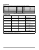
DC-100 Single Scale Note: Units are selectable from lb to kg and can be programmed to weigh in other primary units: lb, kg, g. Capacity Mounting Internal/External Weight Resolution Counting Resolution Platform Dimension 1.0 lb Both 0.0001 0.000001 6" x 8" 2.5 lb Both 0.0002 0.000002 7" x 10" 5.0 lb Both 0.0005 0.000005 12" x 14" 10.0 lb Both 0.001 0.00001 12" x 14" 25.0 lb Both 0.002 0.00002 12" x 14" 50.0 lb Both 0.005 0.00005 12" x 14" Table 1-1.
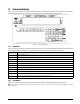
1.2 Modes of Operation 1.2.1 Description of Modes of Operation • Operation Mode – where all the basic weighing and counting operations are performed (also called the Registration Mode). • Report Mode – the report mode is not used in the DC-100 • Program Mode –where item data, factory name, and other data can be programmed into the memory of the scale. • Password Mode – where you can set passwords that will be required for a scale operator to use certain functions of the scale.
DC-100 Mode Flowchart The chart below shows the functions under each of the DC-100 modes. Use the Mode key to switch between modes. Once you are in a particular mode, use the + and – keys to move between the different functions for that mode. 7%)'().
1.3 Keyboard and Display Figure 1-2 shows the DC-100 console with annunciators, function keys and the numeric keypad. Annunciators are described in Section 1.3.1. Section 1.3.2 describes the DC-100 function keys and keypad. Figure 1-2. DC-100 Display 1.3.1 Annunciators Table 1-4 shows a list of the annunciators that the DC-100 uses to provide additional information about the value being displayed. The annunciators are illuminated when the specific function is being performed.
. Key Description Turns the scale display on or off to Used to enter numeric values. When using the scale, first enter a numeric value, then press the appropriate function key.
Key Description Changes the weighing units between lb and kgs. Changes the display between net weight and gross weight. Adds an incrementing Sequence Number to the transaction. Toggle between Inventory In, Inventory Out, and Non-add to Inventory functions. Table 1-5.
2.0 Installation This section describes the procedure for the installation and setup of the DC-100 counting scale. 2.1 Unpacking #AUTION Do not turn scale upside down. Always work with scale on its side! Damage to the load cell can occur if the scale is turned upside down. Immediately after unpacking, visually inspect the DC-100 counting scale to ensure all components are included and undamaged. If any were damaged in shipment, notify Rice Lake Weighing Systems and the shipper immediately.
2.2 Repacking If the DC-100 counting scale must be returned for modification, calibration or repair, it must be properly packed with sufficient cushioning materials. Whenever possible, use the original carton when shipping the DC-100. Damage caused by improper packaging is not covered by the warranty. 2.3 Setting Up Place the scale on a solid, level surface away from fans, breezes, and sources of electrical interference.
2.5 Battery Installation This section covers the installation of the DC-100’s optional battery into the battery compartment. Use the following steps to install a battery into the DC-100. #AUTION Do not turn the scale upside down. Always work with the scale on its side! Damage to the load cell can occur if the scale is turned upside down. 1. Turn the DC-100 on its left side. 2. Unscrew the three screws holding on the side cover to the battery compartment. Screw Location Figure 2-4.
5. Slide the faston connectors on the battery cables onto the faston tabs on the battery, being careful to match the wire color with the colored tag by the faston tabs to insure correct polarity. Figure 2-7. Faston Tabs 6. Place the battery inside the battery compartment. Then replace the battery holder bracket and secure it with the battery slot screw. Figure 2-8. Battery Holder Bracket 7. Replace the side cover to the scale case and secure it with the three screws on the bottom of the scale.
2.6 Start-Up Screens 1. As the scale powers up it will display the current version of the firmware it is using. It also shows that the scale is currently being operated as a stand-alone unit. 2. After a test of the different elements of the display, the scale takes you to the stand-by screen in the Operation Mode. At the stand-by screen the WEIGHT, UNIT WEIGHT and QUANTITY displays show zeroes and the annuciator for the platform you are using is illuminated (A, B, C or D).
2.7 Setting Time and Date Once you set the internal clock for the correct day and time it will continue to keep them, even when the scale is off, using the internal battery on the main board. The procedure below can also be used to adjust the time when moving from Standard to Daylight Savings Time or when the scale is moved to a new facility in a different time zone. Note: SPEC 05 - DATE ORDER and SPEC 06 - TIME FORMAT allow you to set the format for date and time that you prefer the scale to display.
3.0 Configuration Settings This section presents the setup and configuration of the 920i counting scale to be used specifically by distributors and service technicians. Configuring these specifications allow you to tailor the 920i to your specific applications. Setting the specifications allows you to modify the functionality of the 920i. Use the tables in this section to view the options you can modify.
SPEC Description 00 Auto Power Saving When No Weight Change & No Key Press 0: Disable (DEFAULT) 1: 1 minute 2: 2 minutes 3: 3 minutes 4: 4 minutes 5: 5 minutes 6: 6 minutes 7: 7 minutes 8: 8 minutes 9: 9 minutes 10: 10 minutes 11: 11 minutes 12: 12 minutes 13: 13 minutes 14: 14 minutes 15: 15 minutes 01 Power Saving Type When set to 0, the backlight turns off when the scale goes into power-saving mode.
SPEC Description 08 Sampling Times for Unit Weight Calculation Higher number samples improve accuracy in environments of higher vibration or breeze but also increase the time required to compute the unit weight.
SPEC Description 31 PC/PRN Output Data Method 0: No operation 1: Counting 2: By +/-/Print Key (PC/PRN) (DEFAULT) 3: For both classes 1 & 2 32 Select External Printer Type 0: Eltron/TVP (DEFAULT) 1: SE520 2: DP122 (Japan) 3: Epson 33 External Eltron/TVP Printer Download Label Format 0: Enable (DEFAULT) 1: Disable 34 Print When Press +/- Key 0: Disable (DEFAULT) 1: Enable 35 PC Data With Header 0: Yes (DEFAULT) 1: No 36 PC Data Header Type 0: Code 9 - numeric headers (DEFAULT) 1: Title - alphabet
SPEC Description 62 RS232 - XON/XOFF 0: Disable 1: Enable 63 Sample Quantity Determines the number of pieces the scale assumes are on the platter when you press the PIECES key to calculate the Unit Weight. 0: 10 pieces (DEFAULT) 1: 25 pieces 2: 50 pieces 3: 100 pieces 64 Scale A <-> B Sets whether the unit weight determined by sampling on Scale A is automatically transferred to Scale B or not.
SPEC Description 73 Print Barcode This option allows you to print barcodes on labels with all the headers printed, with no headers printed, or with all the headers except the header for the Quantity barcode on label formats with barcode headers included. 0: With Header (DEFAULT) 1: All Without Header 74 Overwrite Unit Weight Allows you to protect the Unit Weight so that it cannot be overwritten by the operator.
Spec Description 604 Weight Decimal Point Position for Scale A 0: 0 1: 0.0 2: 0.00 3: 0.000 (DEFAULT) 4: 0.0000 605 Load Cell Sensitivity Selection in mV/V for Scale A 0: 4.00 mV/V 1: 3.76 mV/V 2: 3.52 mV/V 3: 3.28 mV/V 4: 3.04 mV/V 5: 2.80 mV/V 6: 2.56 mV/V 7: 2.32 mV/V 8: 2.08 mV/V 9: 1.84 mV/V 10: 1.60 mV/V 11: 1.36 mV/V 12: 1.12 mV/V (DEFAULT) 13: 0.88 mV/V 14: 0.64 mV/V 15: 0.
Spec Description 611 Load Cell Sensitivity Selection in mV/V for Scale B 0: 4.00 mV/V 1: 3.76 mV/V 2: 3.52 mV/V 3: 3.28 mV/V 4: 3.04 mV/V 5: 2.80 mV/V 6: 2.56 mV/V 7: 2.32 mV/V 8: 2.08 mV/V 9: 1.84 mV/V 10: 1.60 mV/V 11: 1.36 mV/V 12: 1.12 mV/V (DEFAULT) 13: 0.88 mV/V 14: 0.64 mV/V 15: 0.
Spec Description 617 Load Cell Sensitivity Selection in mV/V for Scale C 0: 4.00 mV/V 1: 3.76 mV/V 2: 3.52 mV/V 3: 3.28 mV/V 4: 3.04 mV/V 5: 2.80 mV/V 6: 2.56 mV/V 7: 2.32 mV/V 8: 2.08 mV/V 9: 1.84 mV/V (DEFAULT) 10: 1.60 mV/V 11: 1.36 mV/V 12: 1.12 mV/V 13: 0.88 mV/V 14: 0.64 mV/V 15: 0.
Spec Description 629 Weight Reset When Tare 0: Yes (DEFAULT) 1: No 630 Auto Clear Tare When Rezero 0: No (DEFAULT) 1: Yes 631 Initial Start Range Settings 0: +/- 2% full scale 1: +/- 10% full scale 632 Zero Range Settings 0: +/- 2% full scale 1: +/- 10% full scale2: 633 Zero Lamp Lighting Method 0: Gross weight (DEFAULT) 1: Net weight 634 Rezero When Changing Scale 0: No rezero (DEFAULT) 1: Rezero 635 Stability Check When Changing Scale 0: Stability check (DEFAULT) 1: No stability check 636
Spec 646 Description Automatic Unit Weight Clear Conditions 0: Disable (DEFAULT) 1: Over net 5D & gross 21D & weight stable 2: >=net 1D & weight stable 3: >=net 1D & quantity > 0 & weight stable Table 3-2.
4.0 Calibration The DC-100 counting scale is a high-precision instrument. Although the scale needs very little maintenance, you may want to check the calibration after every month or so of normal usage. To do this you will need to have a test weight of approximately the total capacity of the scale (i.e. a 10 lb weight if you have a 10 lb capacity scale). After the scale is initially installed, put the weight on the platform and record the weight displayed.
4. The scale display confirms that you are in the Calibration Mode. 5. Next, press the * REPRINT key to enter the zero setting mode. 6. Choose which scale platform you are calibrating. The scale defaults to platform A. To choose another scale platform, press the SCALE key until the platform you want to calibrate is displayed. 7. Make sure that nothing is on the scale platform and press the CODE key to have the scale automatically search for the zero point. 8.
10. Press the * REPRINT key to enter the weight calibration setting. 11. Put a calibrated weight on the platform equal to the total capacity of the scale (Example, for a 25 lb scale, place a 25 lb weight on the scale). Alternatively, you can enter the weight from the numeric keypad. The weight appears in quantity window. Press the * REPRINT key to save the calibration data.
5.0 Scale Operations The following paragraphs contain detailed operator instructions for the DC-100 counting scale (see Figure 5-1). Included are instructions to enter tare weights, toggle between net and gross weight, enter unit weights, perform inventory accumulation and reduction, and toggle between scales. All operator instructions are conducted with the scale in the operation mode that is the weighing or normal mode. Figure 5-1.
5.1 Weight Unit Switching Notes: • SPEC 600 SCALE UNIT SPECIFICATION sets the default weight unit to Grams, Kgs or Lbs. • SPEC 642 WEIGHT/UNIT CONVERT must be set to “0: YES” in order for you to be able to switch weight units during weighing operations. The weight units displayed can be changed between Kg and Lb during weighing operations by pressing the LB/ key. KG 5.2 Entering Tare Weights Tare weights can be entered in the scale by one of two methods: one-touch tare or digital tare.
5.2.3 Tare Addition or Subtraction Two tares can be accumulated or subtracted using the TARE key as well. Tare weights cannot be accumulated or subtracted by digital entry, although you can do tare exchange by digital entry (Section 5.2.4) Notes: • SPEC 620 TARE RANGE must be set to the appropriate tare range value. Default is “0: 100 PERCENT OF FULL SCALE”.
5.4 Entering Unit Weights Entering unit weights can be done either by sampling, as presented in Section 5.4.1, or by key entry as described in Section 5.4.2. Note: SPEC 03 EXTENT OF INSUFFICIENT SAMPLES controls unit weight sampling. The default setting for the percent. SPEC is 0.1 Note: SPEC 63 SAMPLE QUANTITY determines the number of peices the scale assumes are on the platter when you press the PIECES key to calculate the unit weight. The default setting for the SPEC is 0: 10 pieces.
SPEC 7 - Unit Weight Auto-Recomputing Set to “1: Yes” 1. Press REZERO key to zero scale. 2. Place 10 pieces of the item to be sampled on the scale. 3. Press the PIECES key. If the weight of the sample is sufficient (INSUFF annunciator is off), the display shows a unit weight for 10 pieces. However, if the weight of the sample is insufficient ( INSUFF annunciator is on) the display will show ---ADD XX PIECES. Add the indicated number of pieces to the initial sample.
5.5 Part Accumulation and Negative Counting – Without Recalling an Item Code The DC-100 counting scale is fully capable of part number inventory tracking and maintenance using the stored item code function internal to the scale software. See “Inventory Operations Related to the Item Code Quantity” on page 39. Additionally, the scale has the capability to acquire the total number of parts using the accumulation or reduction function of the scale (similar to the add/ subtract functions of a calculator). 5.
press the + key. Note: If SPEC 14 AUTO EXIT FROM ADD MODE is set to “0: No”, the scale will not auto exit from displaying the total amount. To return to the weighing mode, press the CLEAR key. Negative Counting - Total Removed Displayed at the End With this procedure you can count accurately out of a full container for kitting, shipping, etc. without having to know the tare weight of the container. 1. Place a full container on the scale and press TARE. 2.
5.7.2 Subtracting Parts From Inventory 1. Key in the item ID Code and press the CODE key. 2. If the tare weight and unit weight have already been associated with the ID Code in memory, you can go to step 4. Otherwise, key in the known tare weight or scan the tare weight from a barcode or put the empty bin on the scale and press the TARE key. 3. If the unit weight has already been associated with the ID Code in memory, you can go to step 4. Otherwise, place a sample of 10 pieces in the bin on the scale.
6.0 Scale Programming The DC-100 can store information for the parts you count most frequently, eliminating the need for re-entering data during parts counting. With up to 2,000 item code numbers able to be programmed into your 420 Plus counting scale, the scale can act as a stand-alone inventory system. 6.1 Item Code Storage Before beginning to enter data about an item, you need to have defined ahead of time the setpoints you are going to attach to this particular item See Section 6.1.2 on page 37 .
6.1.1 Checking Memory Status To see how many existing items have been programmed and how many items can still be stored, do the following: 1. Press MODE key until the display shows ITEM CODE PROGRAMMING. The S annunciator, indicating the Programming Mode, will illuminate 2. Press the + (plus) or – (minus) keys to scroll through the programming options until you see the memory status screen.
Notes: •There are four types of setpoints which can be selected by rotating through them in the following order using the [+} key: % of Quantity (%QTY), % of Weight (%WT), Over/Under Quantity (QTY), or Over/Under Weight (WT). • When entering weight setpoints, be sure that you enter in the weight values with decimal point and all leading and trailing zeros. • All percentage values must be rounded to the nearest whole number, fractional percentages are not allowed.
6.1.3 Delete Item Memory To just clear an individual field associated with an item code, follow the programming instructions in Section 6.1.2 and press the CLEAR key when the data to be deleted is displayed. Be sure to save your changes at the end of the programming mode by pressing the CODE key.
6.2.2 Re-Computing Item Code Unit Weight Note: If you want the accuracy percentage of the recomputing to be displayed during the calculation, be sure that SPEC 9 DISPLAY ACCURACY UNIT WEIGHT CALCULATION DURING RECOMPUTING is set to “1: YES”. 1. 2. 3. 4. 6.2.3 Recall item code from memory (refer to Section 6.2.1). Place items to be counted on the scale platter until the RECOMPUTING annunciator lights up. Press the PIECES key for recomputing the unit weight. (This may take a few seconds.
2. To add a quantity to inventory, press the STATUS key once. The IN annunciator illuminates. To subtract a quantity from inventory, press the STATUS key twice. The OUT annunciator illuminates. 3. Place the container of parts to be added or subtracted from memory on the scale platter. 4. Press the * REPRINT key to add or subtract the quantity shown on the display to the amount already stored under the item code memory. The display will briefly say PLEASE WAIT…, then return to normal.
6.3 Setting Tare in Operation Mode This section will describe the different tare-related operations you can perform from the operation mode. Tare weight can be set by one touch tare using the TARE key or, if the value is known ahead of time, can be entered digitally using the digital tare function. Tare addition and subtraction can also be done digitally or by using the TARE key. Finally, an existing tare stored with an Item code can be overridden with a new one if needed.
6.4 Setting a Lot Number When storing item codes in the scale’s memory, you have the option to attach a lot number to that item. (See Section 6.1.2) That lot number will appear on an item label unless overridden by setting a new lot number during weighing operations. The procedure below allows the operator to enter and apply a lot number during counting, weighing or packing operations and change lots without having to store a new lot number in each individual item code.
7.0 External Printers, Barcode Scanners, Keyboards and Platforms The following sections decribe connecting external printers, barcode scanners, and keyboards. 7.1 Connecting External Printers An external printer can be connected to interface with the DC-100 scale. 7.1.
Pin Number Description 1 Pin Number Description 1 CTS 2 RXD 2 GND 3 TXD 3 DSR 4 RXD 5 TXD 6 DTR 4 5 GND 6 7 RTS 7 RTS 8 CTS 8 Vcc 9 Table 7-2. Eight-Pin DIN Connector - DC-100 Table 7-1. Nine-Pin DIN Connector - External Printer 7.1.3 Eltron Printers The DC-100 includes a pre-programmed format that works with Eltron printers and printers that emulate the Eltron Use the following steps to hook up the Eltron printer to the DC-100 scale. 1.
7.1.4 Epson Printers The DC-100 includes a pre-programmed format that works with Epson printers and printers that emulate the Epson. Figure 7-3. Epson Printer Label Format 1. Make sure that the following DC-100 spec codes are properly set for printing to the Epson printer as an external printer. • Set SPEC 62 - RS232 - XON/XOFF to 1:Enable. This turns on the handshaking between the scale and printer that allows the label format in the DC-100 to be downloaded to the Epson printer at the time you print.
7.2.1 Header Codes Data can be input with headers or without them. The following header codes are the ones recognized by the DC-100: Header Code ASCII Code Data 1 31 Unit Weight 2 32 Quantity 3 33 ID Code 4 34 Tare Weight A 41 Gross Weight E 45 Lot Number F 46 Set Point 1 (Weight) G 47 Setpoint 1 (Quantity) H 48 Setpoint 2 I 49 Total Quantity K 4B Inventory M 4D Part Number N 4E Part Name Table 7-3.
7.2.2 Z Commands via Barcodes You can also scan barcode representations of the scale’s Z commands. This allows the scale operator to use the scanner to initiate certain scanner functions: Z Command Function Z0 Rezero Z1 Print Z2 Unit Weight Clear Z3 Plus Z4 Minus Z5 Tare Z6 Clear ZS1 Scale 1 ZS2 Scale 2 ZS3 Scale 3 ZS4 Scale 4 Table 7-4. Z Command Functions 7.2.
7.2.6 Programming the QSC-6000 Plus Quickscan RS232C Scanner If you are using the Quickscan RS232C barcode scanner sold by Rice Lake Weighing Systems for DIGI scales, scan the following bar codes to set the scanner for proper communication with the DC-100. 1. Set to RS232 default values and enable RS232 interface Warning: use this barcode with caution because it will clear any features you may have programmed since the scanner’s installation and reset them all to the defaults. 2.
3. Set Handshaking Requirements Disable hardware handshaking Disable CTS/RTS flow control Disable XON/XOFF software handshaking Set Disable Hardware Disable CTS/RTS Disable Xon/Xoff End 4.
5. Set Interchange Delay 0 milliseconds Set 0 Milliseconds End 6. Disable ACK/NAK Set Disable ACK/NAK End 7.
8. Set Label ID disable ID control Set Disable ID Control End 9.
10.
7.2.7 Programming the QuickScan Keyboard Wedge Scanner If you are using the Quickscan keyboard wedge barcode scanner connected to the IBM keyboard port as described in Section 7.3 on the following page, scan the following barcodes to set up your scanner to communicate with the DC-100. 1. Set to RS232 Default Values warning: use this barcode with caution because it will clear any features you may have programmed since the scanner’s installation and reset them all to the defaults. 2.
7.3 Connecting the IBM Keyboard The DC-100 can be connected to an IBM PC/AT keyboard to speed data entry in the operation and programming modes. The keyboard connects to the scale at the port labeled IBM KEYBD. Set SPEC 37: IBM KEYBOARD PORT to 0: IBM KEYBOARD. Note: For instructions on how to set the customer specifications, refer to Section 3.1.
7.4 Connecting an External Platform For a list of DIGI remote platforms that can be used with the DC-100, see Table 1-2 on page 2. Figure 7-4. Fourteen-Pin Amphenol Female Pin Number Remote Platform Connector Description 1 Not used 2 Not used 3 + Excitation 4 - Excitation 5 6 + Signal 7 - Signal 8 Shield 9 through 14 Not used Table 7-8.
8.0 Job Sequence Programming The ability to program a series of instructions for the operators that appear on the display is one of the most useful features of the DC-100. The scale can be made easy to use even for operators not familiar with all of its features, ensuring accuracy by increasing consistency and avoiding operator error. Up to 10 job sequence steps can be programmed to be displayed in order, with each instruction having up to 22 characters.
press the CLEAR key once as the last step. If you want the job sequence to start over again once the task is done, prompt the operator to press the CLEAR key twice as the last step. 7. Repeat Steps 3-6 above until you have programmed all the steps you want. To exit programming mode and return to the stand-by screen, press the MODE key twice. At the stand-by screen you will see the prompt for the first step in the job sequence flashing on the second line of the display. 8.
8.4 Deleting a Job Sequence Step This function allows you to delete a step that is no longer necessary in the job sequence programming. 1. Press MODE key until the display shows ITEM CODE PROGRAMMING. The S annunciator, indicating the programming mode, will illuminate 2. Press the + or - key until you reach the program job sequence mode. 3. Enter the job sequence number of the step you want to delete. Instead of pressing the * REPRINT key to go into the programming of that step, press the - key.
9.0 Password Protecting the Programming Functions In some situations it may be useful to password protect certain functions of the scale so that they can only be used by authorized personnel. Each of the major modes of the scale other than the operation mode can be set to require a password of up to six numeric digits. The ability to set, change or delete passwords in the password mode itself should also be password protected.
key without entering anything. You will be prompted to choose one of these options for each mode for which a password can be programmed. 4. Once all of the passwords have been modified, cleared or reconfirmed, the scale will return to the operation mode. Press the MODE key five times to return to the Stand-by screen.
10.0 DC-100 Error Message List The DC-100’s two-line alphanumeric display allows for detailed error messages. Use Table 10-1 below to find the error message, possible causes for the error and ways to correct the problem. If these suggestions fail to correct the situation, please contact your DIGI dealer for assistance.
Error Message Possible Causes Corrective Action Scale C start up err press clr key to exit Unable to detect scale C because it is not stable or the weight on the platform is out of the scale start-up range. Press Clear key to exit. Bring the weight on the platform down to within the start-up range Force balance error press clr key to exit Unable to detect a force balance during start-up. Press the Clear key to exit Check the connection between the scale and the balance. Table 10-1.
11.0 DC-100 Limited Warranty Rice Lake Weighing Systems (RLWS) warrants that all RLWS equipment and systems properly installed by a Distributor or Original Equipment Manufacturer (OEM) will operate per written specifications as confirmed by the Distributor/OEM and accepted by RLWS. All systems and components are warranted against defects in materials and workmanship for one year. RLWS warrants that the equipment sold hereunder will conform to the current written specifications authorized by RLWS.
DC-100 Limited Warranty 65