
Specifications


Table Of Contents
- About This Manual
- 1.0 Introduction
- 2.0 Installation
- 3.0 Configuration Settings
- 4.0 Calibration
- 5.0 Scale Operations
- 5.1 Weight Unit Switching
- 5.2 Entering Tare Weights
- 5.2.1 One-Touch Tare, Tare Unknown
- 5.2.2 Digital Tare, Tare Weight Known
- 5.2.3 Tare Addition or Subtraction
- 5.2.4 Tare Exchange
- 5.3 Toggling Between Gross and Net
- 5.4 Entering Unit Weights
- 5.4.1 Unit Weight Operation by Sampling
- 5.4.2 Unit Weight Operation by Key Entry
- 5.5 Part Accumulation and Negative Counting - Without Recalling an Item Code
- 5.5.1 Part Accumulation
- 5.5.2 Negative Counting
- 5.5.3 Clearing Accumulated Data
- 5.6 Toggle Between Scales
- 5.7 Adding Parts To and Subtracting Parts From Inventory
- 5.7.1 Adding Parts to Inventory
- 5.7.2 Subtracting Parts From Inventory
- 5.7.3 Sample, Count and Print a Label
- 5.7.4 Scan ID Bar Code, Count and Print a Label
- 6.0 Scale Programming
- 6.1 Item Code Storage
- 6.1.1 Checking Memory Status
- 6.1.2 Program ID Code, Unit Weight, Tare Weight, Label Format, Part Name, Part Number, Lot Number, Location, Inventory Quantity, Threshold, and Setpoints
- 6.1.3 Delete Item Memory
- 6.2 Using Item Codes in Normal or Operation Mode
- 6.2.1 Recalling Numeric Item Codes using Item Code Number
- 6.2.2 Re-Computing Item Code Unit Weight
- 6.2.3 Quick Add Item to Memory
- 6.2.4 Tare Override
- 6.2.5 Inventory Operations Related to the Item Code Quantity
- 6.2.6 Delete Item Memory
- 6.3 Setting Tare in Operation Mode
- 6.3.1 One Touch Tare
- 6.3.2 Digital Tare (When Tare Weight is Known in Advance)
- 6.3.3 Tare Value Exchange (Tare Addition or Subtraction)
- 6.4 Setting a Lot Number
- 6.5 Setting a Sequence Number
- 7.0 External Printers, Barcode Scanners, Keyboards and Platforms
- 7.1 Connecting External Printers
- 7.1.1 SPEC Settings for External Printers
- 7.1.2 Connecting the Printer to the RS-232C Port
- 7.1.3 Eltron Printers
- 7.1.4 Epson Printers
- 7.2 Connecting a Barcode Scanner
- 7.2.1 Header Codes
- 7.2.2 Z Commands via Barcodes
- 7.2.3 Configuring the RS232C Port for a Scanner
- 7.2.4 Connecting the Scanner to the RS232C Port
- 7.2.5 Configuring the Keyboard Port for a Scanner
- 7.2.6 Programming the QSC-6000 Plus Quickscan RS232C Scanner
- 7.2.7 Programming the QuickScan Keyboard Wedge Scanner
- 7.3 Connecting the IBM Keyboard
- 7.4 Connecting an External Platform
- 8.0 Job Sequence Programming
- 9.0 Password Protecting the Programming Functions
- 10.0 DC-100 Error Message List
- 11.0 DC-100 Limited Warranty
8 DC-100 Operation Manual
2.0 Installation
This section describes the procedure for the installation and setup of the DC-100 counting scale.
2.1 Unpacking
Do not turn scale upside down. Always work with scale on its side! Damage to the load cell can occur if
the scale is turned upside down.
Immediately after unpacking, visually inspect the DC-100 counting scale to ensure all components are included
and undamaged. If any were damaged in shipment, notify Rice Lake Weighing Systems and the shipper
immediately.
The DC-100 counting scale is packed in custom-fitted foam. After opening the box, remove all the components.
Check the insides of the box carefully to make sure you have all of the pieces. The package should include the
following:
• DC-100 counting scale
• Stainless steel platter
• AC power cord
• DIGI certificate of quality
• Spare keysheet label
Figure 2-1. DC-100 Unpacked
Remove the bag protecting the scale and the dessicant bag. Next remove the protective film covering the front
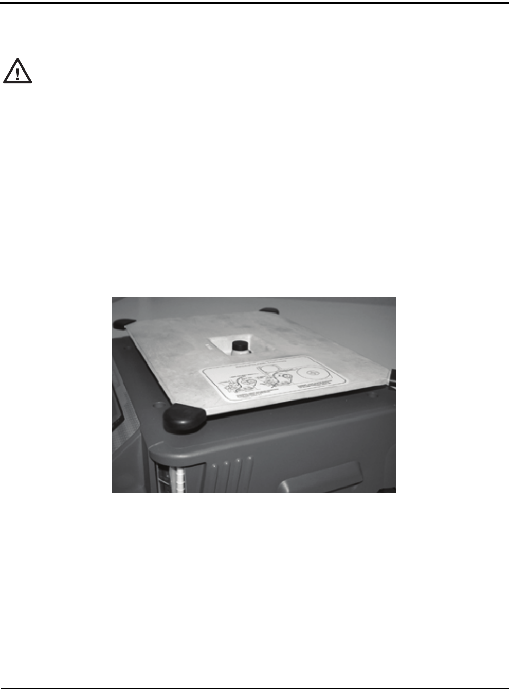
panel and the foam spacers between the scale case and the platform spider. Finally, place the stainless steel
platter on top of the scale and seat it securely on the rubber stops.
After insuring that all the parts are present, store the original box in a safe location for possible future use. You
will want the original packaging if you ever need to transport the scale or send it for servicing.
#AUTION