
Specifications


Table Of Contents
- About This Manual
- 1.0 Introduction
- 2.0 Installation
- 3.0 Configuration Settings
- 4.0 Calibration
- 5.0 Scale Operations
- 5.1 Weight Unit Switching
- 5.2 Entering Tare Weights
- 5.2.1 One-Touch Tare, Tare Unknown
- 5.2.2 Digital Tare, Tare Weight Known
- 5.2.3 Tare Addition or Subtraction
- 5.2.4 Tare Exchange
- 5.3 Toggling Between Gross and Net
- 5.4 Entering Unit Weights
- 5.4.1 Unit Weight Operation by Sampling
- 5.4.2 Unit Weight Operation by Key Entry
- 5.5 Part Accumulation and Negative Counting - Without Recalling an Item Code
- 5.5.1 Part Accumulation
- 5.5.2 Negative Counting
- 5.5.3 Clearing Accumulated Data
- 5.6 Toggle Between Scales
- 5.7 Adding Parts To and Subtracting Parts From Inventory
- 5.7.1 Adding Parts to Inventory
- 5.7.2 Subtracting Parts From Inventory
- 5.7.3 Sample, Count and Print a Label
- 5.7.4 Scan ID Bar Code, Count and Print a Label
- 6.0 Scale Programming
- 6.1 Item Code Storage
- 6.1.1 Checking Memory Status
- 6.1.2 Program ID Code, Unit Weight, Tare Weight, Label Format, Part Name, Part Number, Lot Number, Location, Inventory Quantity, Threshold, and Setpoints
- 6.1.3 Delete Item Memory
- 6.2 Using Item Codes in Normal or Operation Mode
- 6.2.1 Recalling Numeric Item Codes using Item Code Number
- 6.2.2 Re-Computing Item Code Unit Weight
- 6.2.3 Quick Add Item to Memory
- 6.2.4 Tare Override
- 6.2.5 Inventory Operations Related to the Item Code Quantity
- 6.2.6 Delete Item Memory
- 6.3 Setting Tare in Operation Mode
- 6.3.1 One Touch Tare
- 6.3.2 Digital Tare (When Tare Weight is Known in Advance)
- 6.3.3 Tare Value Exchange (Tare Addition or Subtraction)
- 6.4 Setting a Lot Number
- 6.5 Setting a Sequence Number
- 7.0 External Printers, Barcode Scanners, Keyboards and Platforms
- 7.1 Connecting External Printers
- 7.1.1 SPEC Settings for External Printers
- 7.1.2 Connecting the Printer to the RS-232C Port
- 7.1.3 Eltron Printers
- 7.1.4 Epson Printers
- 7.2 Connecting a Barcode Scanner
- 7.2.1 Header Codes
- 7.2.2 Z Commands via Barcodes
- 7.2.3 Configuring the RS232C Port for a Scanner
- 7.2.4 Connecting the Scanner to the RS232C Port
- 7.2.5 Configuring the Keyboard Port for a Scanner
- 7.2.6 Programming the QSC-6000 Plus Quickscan RS232C Scanner
- 7.2.7 Programming the QuickScan Keyboard Wedge Scanner
- 7.3 Connecting the IBM Keyboard
- 7.4 Connecting an External Platform
- 8.0 Job Sequence Programming
- 9.0 Password Protecting the Programming Functions
- 10.0 DC-100 Error Message List
- 11.0 DC-100 Limited Warranty
Installation 9
2.2 Repacking
If the DC-100 counting scale must be returned for modification, calibration or repair, it must be properly packed
with sufficient cushioning materials. Whenever possible, use the original carton when shipping the DC-100.
Damage caused by improper packaging is not covered by the warranty.
2.3 Setting Up
Place the scale on a solid, level surface away from fans, breezes, and sources of electrical interference.
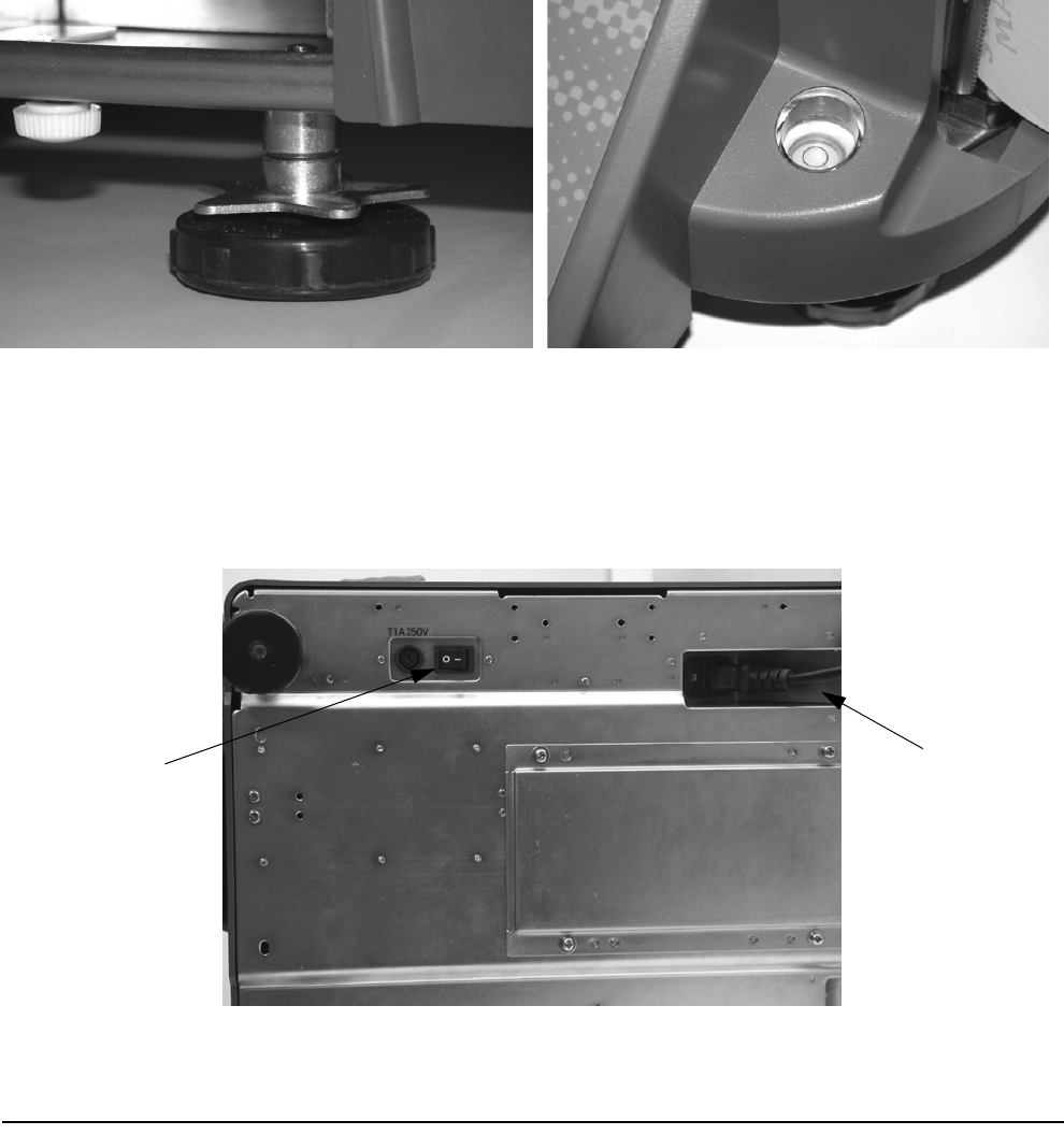
Level the scale by turning the four adjustable legs located on the bottom of the scale while referencing the bubble
level located on the front of the scale (see
Figure 2-2).
Note:To ensure a higher degree of scale stability, turn in all four adjustable legs before leveling. Turn out adjustable legs to level
as needed.
Figure 2-2. Leveling Feet and Bubble
2.4 Powering Up the DC-100
After plugging the power cord into the socket on the bottom of the scale (Figure 2-3) turn the power switch on
the back of the bottom of the scale to the ON position. Generally when starting up the scale, if the power switch is
currently
OFF, turning it to the ON position powers up the scale. If the power switch is already in the ON position
but the display has been powered down by pressing the
ON/OFF key on the front, the scale can be reactivated by
pressing the
ON/OFF key again.
Figure 2-3. Power Switch and Power Cord Location
Power switch
location
Power cord
location