
Specifications


Table Of Contents
- About This Manual
- 1.0 Introduction
- 2.0 Installation
- 3.0 Configuration Settings
- 4.0 Calibration
- 5.0 Scale Operations
- 5.1 Weight Unit Switching
- 5.2 Entering Tare Weights
- 5.2.1 One-Touch Tare, Tare Unknown
- 5.2.2 Digital Tare, Tare Weight Known
- 5.2.3 Tare Addition or Subtraction
- 5.2.4 Tare Exchange
- 5.3 Toggling Between Gross and Net
- 5.4 Entering Unit Weights
- 5.4.1 Unit Weight Operation by Sampling
- 5.4.2 Unit Weight Operation by Key Entry
- 5.5 Part Accumulation and Negative Counting - Without Recalling an Item Code
- 5.5.1 Part Accumulation
- 5.5.2 Negative Counting
- 5.5.3 Clearing Accumulated Data
- 5.6 Toggle Between Scales
- 5.7 Adding Parts To and Subtracting Parts From Inventory
- 5.7.1 Adding Parts to Inventory
- 5.7.2 Subtracting Parts From Inventory
- 5.7.3 Sample, Count and Print a Label
- 5.7.4 Scan ID Bar Code, Count and Print a Label
- 6.0 Scale Programming
- 6.1 Item Code Storage
- 6.1.1 Checking Memory Status
- 6.1.2 Program ID Code, Unit Weight, Tare Weight, Label Format, Part Name, Part Number, Lot Number, Location, Inventory Quantity, Threshold, and Setpoints
- 6.1.3 Delete Item Memory
- 6.2 Using Item Codes in Normal or Operation Mode
- 6.2.1 Recalling Numeric Item Codes using Item Code Number
- 6.2.2 Re-Computing Item Code Unit Weight
- 6.2.3 Quick Add Item to Memory
- 6.2.4 Tare Override
- 6.2.5 Inventory Operations Related to the Item Code Quantity
- 6.2.6 Delete Item Memory
- 6.3 Setting Tare in Operation Mode
- 6.3.1 One Touch Tare
- 6.3.2 Digital Tare (When Tare Weight is Known in Advance)
- 6.3.3 Tare Value Exchange (Tare Addition or Subtraction)
- 6.4 Setting a Lot Number
- 6.5 Setting a Sequence Number
- 7.0 External Printers, Barcode Scanners, Keyboards and Platforms
- 7.1 Connecting External Printers
- 7.1.1 SPEC Settings for External Printers
- 7.1.2 Connecting the Printer to the RS-232C Port
- 7.1.3 Eltron Printers
- 7.1.4 Epson Printers
- 7.2 Connecting a Barcode Scanner
- 7.2.1 Header Codes
- 7.2.2 Z Commands via Barcodes
- 7.2.3 Configuring the RS232C Port for a Scanner
- 7.2.4 Connecting the Scanner to the RS232C Port
- 7.2.5 Configuring the Keyboard Port for a Scanner
- 7.2.6 Programming the QSC-6000 Plus Quickscan RS232C Scanner
- 7.2.7 Programming the QuickScan Keyboard Wedge Scanner
- 7.3 Connecting the IBM Keyboard
- 7.4 Connecting an External Platform
- 8.0 Job Sequence Programming
- 9.0 Password Protecting the Programming Functions
- 10.0 DC-100 Error Message List
- 11.0 DC-100 Limited Warranty
12 DC-100 Operation Manual
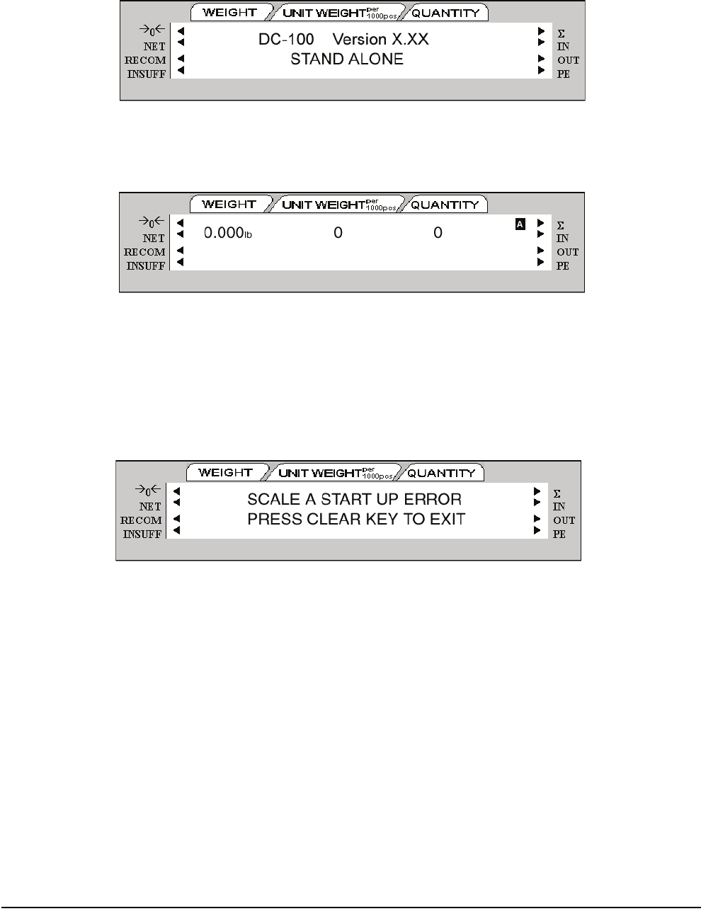
2.6 Start-Up Screens
1. As the scale powers up it will display the current version of the firmware it is using. It also shows that the
scale is currently being operated as a stand-alone unit.
2. After a test of the different elements of the display, the scale takes you to the stand-by screen in the
Operation Mode. At the stand-by screen the
WEIGHT, UNIT WEIGHT and QUANTITY displays show zeroes
and the annuciator for the platform you are using is illuminated (A, B, C or D).
From this stand-by screen all of the basic weighing, counting and inventory operations can be performed.
Also, if any job sequence instructions have been programmed into the scale, the first operator instruction
will be displayed on the second line of the display (
See Section 8.0 on page 56).
3. If there is anything on the platform(s) and it exceeds the scale start range, a beep sounds, and the
following error message appears.
Note: The Initial Start Range settings are controlled by SPEC 631. The default setting is 0: +UNLIMITED TO 10% OF FULL
SCALE
.
Remove the weight from the platform and press the CLEAR key to exit.