
Specifications


Table Of Contents
- About This Manual
- 1.0 Introduction
- 2.0 Installation
- 3.0 Configuration Settings
- 4.0 Calibration
- 5.0 Scale Operations
- 5.1 Weight Unit Switching
- 5.2 Entering Tare Weights
- 5.2.1 One-Touch Tare, Tare Unknown
- 5.2.2 Digital Tare, Tare Weight Known
- 5.2.3 Tare Addition or Subtraction
- 5.2.4 Tare Exchange
- 5.3 Toggling Between Gross and Net
- 5.4 Entering Unit Weights
- 5.4.1 Unit Weight Operation by Sampling
- 5.4.2 Unit Weight Operation by Key Entry
- 5.5 Part Accumulation and Negative Counting - Without Recalling an Item Code
- 5.5.1 Part Accumulation
- 5.5.2 Negative Counting
- 5.5.3 Clearing Accumulated Data
- 5.6 Toggle Between Scales
- 5.7 Adding Parts To and Subtracting Parts From Inventory
- 5.7.1 Adding Parts to Inventory
- 5.7.2 Subtracting Parts From Inventory
- 5.7.3 Sample, Count and Print a Label
- 5.7.4 Scan ID Bar Code, Count and Print a Label
- 6.0 Scale Programming
- 6.1 Item Code Storage
- 6.1.1 Checking Memory Status
- 6.1.2 Program ID Code, Unit Weight, Tare Weight, Label Format, Part Name, Part Number, Lot Number, Location, Inventory Quantity, Threshold, and Setpoints
- 6.1.3 Delete Item Memory
- 6.2 Using Item Codes in Normal or Operation Mode
- 6.2.1 Recalling Numeric Item Codes using Item Code Number
- 6.2.2 Re-Computing Item Code Unit Weight
- 6.2.3 Quick Add Item to Memory
- 6.2.4 Tare Override
- 6.2.5 Inventory Operations Related to the Item Code Quantity
- 6.2.6 Delete Item Memory
- 6.3 Setting Tare in Operation Mode
- 6.3.1 One Touch Tare
- 6.3.2 Digital Tare (When Tare Weight is Known in Advance)
- 6.3.3 Tare Value Exchange (Tare Addition or Subtraction)
- 6.4 Setting a Lot Number
- 6.5 Setting a Sequence Number
- 7.0 External Printers, Barcode Scanners, Keyboards and Platforms
- 7.1 Connecting External Printers
- 7.1.1 SPEC Settings for External Printers
- 7.1.2 Connecting the Printer to the RS-232C Port
- 7.1.3 Eltron Printers
- 7.1.4 Epson Printers
- 7.2 Connecting a Barcode Scanner
- 7.2.1 Header Codes
- 7.2.2 Z Commands via Barcodes
- 7.2.3 Configuring the RS232C Port for a Scanner
- 7.2.4 Connecting the Scanner to the RS232C Port
- 7.2.5 Configuring the Keyboard Port for a Scanner
- 7.2.6 Programming the QSC-6000 Plus Quickscan RS232C Scanner
- 7.2.7 Programming the QuickScan Keyboard Wedge Scanner
- 7.3 Connecting the IBM Keyboard
- 7.4 Connecting an External Platform
- 8.0 Job Sequence Programming
- 9.0 Password Protecting the Programming Functions
- 10.0 DC-100 Error Message List
- 11.0 DC-100 Limited Warranty
44 DC-100 Operation Manual
7. 0 External Printers, Barcode Scanners, Keyboards and Platforms
The following sections decribe connecting external printers, barcode scanners, and keyboards.
7.1 Connecting External Printers
An external printer can be connected to interface with the DC-100 scale.
7.1.1 SPEC Settings for External Printers
In order for the DC-100 scale to recognize an external printer properly and send data to it, there are customer
specifications which must be set properly as follows:
Note: For instructions on how to set the DC-100’s customer specifications, refer to Section 3.1.
• SPEC 15: SIO Select job to 3:PRINTER
• SPEC 16: Baud Rates (SIO) to the proper baud rate for your application
• SPEC 17: Data Length (SIO) to the proper length for your application
• SPEC 18: Parity Bit (SIO) to the proper setting for your application
• SPEC 19: Stop Bit (SIO) to the proper setting for your application
• SPEC 32: Type of Printer to the type of external printer you are using
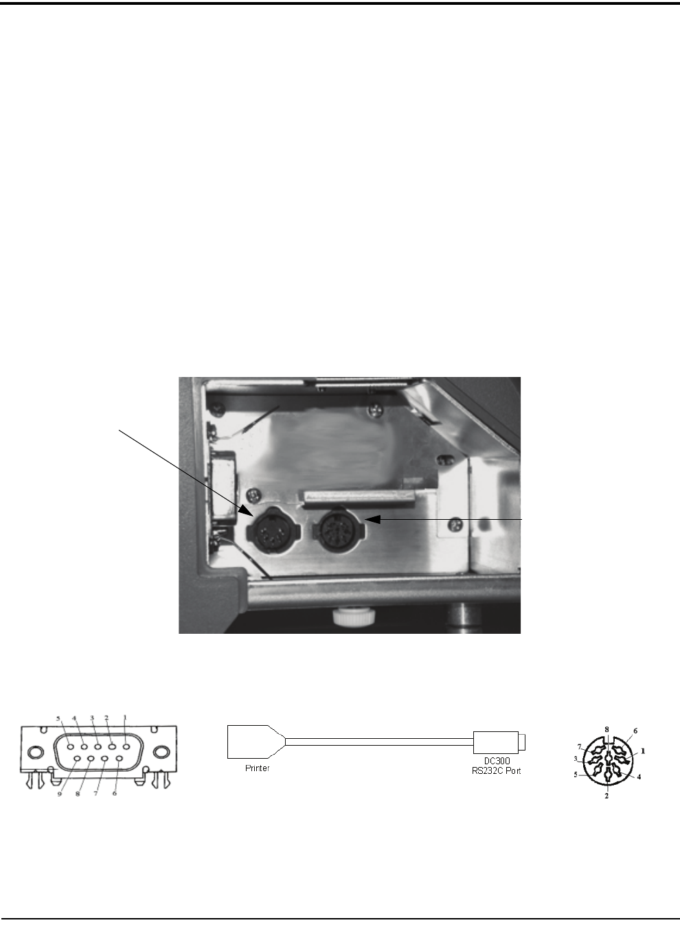
7.1.2 Connecting the Printer to the RS-232C Port
The DC-100 can be connected to an external printer using the main RS-232C port next to the keyboard port as
shown below.
Figure 7-1. DC-100 Interface Port Locations
Figure 7-2. Connection from Scale to Printer
Keyboard port
RS-232 Port for
connecting an
external printer