
Specifications


Table Of Contents
- About This Manual
- 1.0 Introduction
- 2.0 Installation
- 3.0 Configuration Settings
- 4.0 Calibration
- 5.0 Scale Operations
- 5.1 Weight Unit Switching
- 5.2 Entering Tare Weights
- 5.2.1 One-Touch Tare, Tare Unknown
- 5.2.2 Digital Tare, Tare Weight Known
- 5.2.3 Tare Addition or Subtraction
- 5.2.4 Tare Exchange
- 5.3 Toggling Between Gross and Net
- 5.4 Entering Unit Weights
- 5.4.1 Unit Weight Operation by Sampling
- 5.4.2 Unit Weight Operation by Key Entry
- 5.5 Part Accumulation and Negative Counting - Without Recalling an Item Code
- 5.5.1 Part Accumulation
- 5.5.2 Negative Counting
- 5.5.3 Clearing Accumulated Data
- 5.6 Toggle Between Scales
- 5.7 Adding Parts To and Subtracting Parts From Inventory
- 5.7.1 Adding Parts to Inventory
- 5.7.2 Subtracting Parts From Inventory
- 5.7.3 Sample, Count and Print a Label
- 5.7.4 Scan ID Bar Code, Count and Print a Label
- 6.0 Scale Programming
- 6.1 Item Code Storage
- 6.1.1 Checking Memory Status
- 6.1.2 Program ID Code, Unit Weight, Tare Weight, Label Format, Part Name, Part Number, Lot Number, Location, Inventory Quantity, Threshold, and Setpoints
- 6.1.3 Delete Item Memory
- 6.2 Using Item Codes in Normal or Operation Mode
- 6.2.1 Recalling Numeric Item Codes using Item Code Number
- 6.2.2 Re-Computing Item Code Unit Weight
- 6.2.3 Quick Add Item to Memory
- 6.2.4 Tare Override
- 6.2.5 Inventory Operations Related to the Item Code Quantity
- 6.2.6 Delete Item Memory
- 6.3 Setting Tare in Operation Mode
- 6.3.1 One Touch Tare
- 6.3.2 Digital Tare (When Tare Weight is Known in Advance)
- 6.3.3 Tare Value Exchange (Tare Addition or Subtraction)
- 6.4 Setting a Lot Number
- 6.5 Setting a Sequence Number
- 7.0 External Printers, Barcode Scanners, Keyboards and Platforms
- 7.1 Connecting External Printers
- 7.1.1 SPEC Settings for External Printers
- 7.1.2 Connecting the Printer to the RS-232C Port
- 7.1.3 Eltron Printers
- 7.1.4 Epson Printers
- 7.2 Connecting a Barcode Scanner
- 7.2.1 Header Codes
- 7.2.2 Z Commands via Barcodes
- 7.2.3 Configuring the RS232C Port for a Scanner
- 7.2.4 Connecting the Scanner to the RS232C Port
- 7.2.5 Configuring the Keyboard Port for a Scanner
- 7.2.6 Programming the QSC-6000 Plus Quickscan RS232C Scanner
- 7.2.7 Programming the QuickScan Keyboard Wedge Scanner
- 7.3 Connecting the IBM Keyboard
- 7.4 Connecting an External Platform
- 8.0 Job Sequence Programming
- 9.0 Password Protecting the Programming Functions
- 10.0 DC-100 Error Message List
- 11.0 DC-100 Limited Warranty
Introduction 5
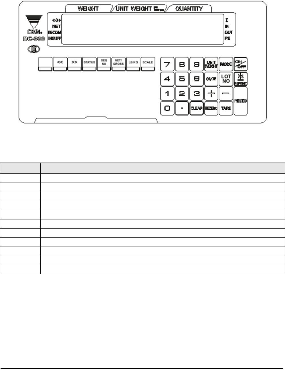
1.3 Keyboard and Display
Figure 1-2 shows the DC-100 console with annunciators, function keys and the numeric keypad. Annunciators
are described in Section 1.3.1. Section 1.3.2 describes the DC-100 function keys and keypad.
Figure 1-2. DC-100 Display
1.3.1 Annunciators
Table 1-4 shows a list of the annunciators that the DC-100 uses to provide additional information about the value
being displayed. The annunciators are illuminated when the specific function is being performed.
1.3.2 Key Functions
Table 1-5 lists the keys and key functions of the DC-100 keyboard and keypad (see Figure 1-2 above).
Note: Some keys have different functions depending on what mode you are in, so be sure to check which mode is selected
before using them.
Annunciator Annunciator Meaning
→ 0 ←
Gross weight is zero
NET
Display shows net weight (when tare weight is entered or recalled)
RECOM
Unit weight is recomputing is possible
INSUFF
Net weight is below specified percentage of scale capacity
²
Memory indicator showing quantity accumulation is being done
IN
Inventory IN (for counting mode)
OUT
Inventory OUT (for counting mode)
R
Scale is in Registration Mode, also referred to as Operation Mode. (see Section 1.2 for description of modes)
S
Scale is in Programming Mode. (see Section 1.2 for description of modes)
X
Scale is in Report Mode. (see Section 1.2 for description of modes)
Z
Scale is in Service Mode. (see Section 1.2 for description of modes)
Table 1-4. DC-100 Annunciators and Function