Edgeport ® USB EXPANSION MODULES INDUSTRIAL Installation Guide Models: Edgeport/1i Edgeport/2i Edgeport/2s Edgeport/4s Edgeport/4s Edgeport/8s MEI MEI DC Isolated MEI www.digi.
Table of Contents Table of Contents ...............................................................................................2 Edgeport/1i.........................................................................................................1 Edgeport/2i.........................................................................................................2 Edgeport/2s MEI, Edgeport/4s MEI,Edgeport/4s Isolated, Edgeport/8s MEI...4 Edgeport Driver Installation .......................................
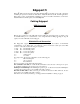
Edgeport/1i Edgeport USB-to-Serial Converters from Digi International provide high-speed serial connectivity via USB port expansion for Windows 2003 Server, 2000, XP, NT 4.0, 98, SE, and Me applications. Edgeport/1i provides one RS-422/485 serial DB-9 port. For more detailed information, as well as the latest manual and technical updates, visit www.digi.com.
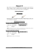
Edgeport/2i Edgeport USB-to-Serial Converters from Digi International provide high-speed serial connectivity via USB port expansion for Windows 2000, XP, NT 4.0, 98, SE, and Me applications. Edgeport/2i provides a combination of up to two RS-422 and/or RS-485 serial DB-9 ports. For more detailed information, as well as the latest manual and technical updates, visit www.digi.com.
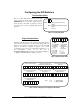
Configuring the DIP Switches Two Position Switch The two position DIP switch, located on the back panel, connects the signal ground to chassis ground. IMPORTANT: Do not connect signal ground to chassis ground on more than one location in order to prevent ground loops and potentially high currents (figure 1).
Edgeport/2s MEI, Edgeport/4s MEI, Edgeport/4s Isolated, Edgeport/8s MEI Edgeport USB-to-Serial Converters from Digi International provide high-speed serial connectivity via USB port expansion for Windows 2000, XP, NT 4.0, 98, 95, SE, and Me applications. Edgeport/2s MEI, Edgeport/4s MEI and Edgeport/8s MEI provide a combination of up to two, four or eight (respectively) RS-232 and/or RS-422 and/or RS-485 serial DB-9 ports.
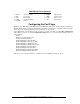
DB9 RS-232 Pin Assignment 1 DCD 2 RD 3 TD 4 DTR 5 SGND data carrier detect receive data transmit data data terminal ready ground 6 DSR 7 RTS 8 CTS 9 RI data set ready request to send clear to send ring indicator Configuring the Port Flags The Edgeport/2s MEI, Edgeport/4s MEI, Edgeport/8s MEI and the Edgeport/4s Isolated, which support RS-232, RS-422 and RS-485, are configured using the Edgeport Utility program.
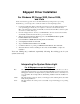
Edgeport Driver Installation For Windows XP, Server 2003, Server 2008, and Vista Note: You must be logged into an account with administrator privileges before proceeding. Note: Please go to www.digi.com to download software for older Operating Systems. 1. Connect the USB cable. (Refer to the Table of Contents to locate the cabling instructions for your specific Edgeport model.
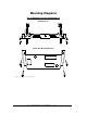
Mounting Diagrams For all Edgeports except the Edgeport/1i Rack Mount Kit* Under-Shelf Mounting Bracket* *Nuts, bolts, and screws are not included. Edgeport Industrial Installation Guide (90000409 Rev.
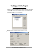
The Edgeport Utility Program For All Windows Operating Systems The Edgeport configuration utility program (edgeport.exe) allows you to manage the serial ports of your Edgeport product. Note that with Windows NT you must have administrative privileges in order to change the COM port settings. For more information, see the Support section at www.digi.com. General Tab The General tab in this utility allows you to do the following: Information - Check the manufacturing information pertaining to your device.
Configure - Reassign the physical port on your device to any available Windows COM port number from 1 to 255 and give your device a user friendly Device Name. This capability is particularly helpful if you have more than one device. Port Flags - Configure performance options and special functionality on a per-port basis. Edgeport Industrial Installation Guide (90000409 Rev.
Low Latency: (930 based Edgeport only) Normally the UART will interrupt when the receiver has been idle for 4 character times. (For example 4ms at 9600) As long as data is being received the UART will continue to buffer them until its internal FIFO is full (~56 bytes). This flag causes the Edgeport to poll the RX FIFO for received bytes. If any bytes are available they will be sent to the driver without any delay.
Test Ports - Perform a confidence test on the internal workings of the serial ports. Power Management – Turn on and off the power for Hubports with USB PlusPower ports Edgeport Industrial Installation Guide (90000409 Rev.
Port Status – Provide the status of a selected (highlighted) serial port. The Poll Interval is the number of seconds between updates of this window. This is also the number of seconds between each entry in the log file. To create a log file, click the Start Logging button and enter a filename for the log file. This file will contain all of the information displayed in the Port Status window until the Stop Logging button is clicked. Refresh – Scan for ports. Note that NT 4.0 does not automatically scan.
Uninstall the drivers. Enable Event Logging – Place event messages in system event log. Configure how COM ports will be assigned. The driver supports COM port number assignment in two ways: 1. Assign COM ports based on converter serial number. This is the default setting. In this mode, the driver uses the serial number of each converter to uniquely identify it, and the COM port assignments for a given converter are based on its serial number.
Understanding Hubs Hubs, critical components in the USB architecture, are wiring concentrators that enable the attachment of multiple devices, thus converting a single attachment point into multiple attachment points. USB architecture allows a cascaded multiple hub configuration with certain power limitations (explained later in this section). See figure 1.
Regulatory & Other Information © 2006 Digi, Digi International, the Digi logo, the Digi Connectware logo, Edgeport, and Hubport are either trademarks or registered trademarks of Digi International, Inc. in the United States and/or other countries. All other trademarks are the property of their respective holders. Information in this documentation is subject to change without notice and does not represent a commitment on the part of Digi International.
declares that the product Product Name(s): Edgeport/1i Model Number(s): 301-1001-31 Product Name(s): Edgeport/2i Model Number(s): 301-1000-12 Product Name: Edgeport/2s MEI Model Number(s): 301-1000-92 Product Name: Edgeport/4s MEI Model Number(s): 301-1000-94 Product Name: Edgeport/4s Isolated Model Number(s): 301-1000-95 Product Name: Edgeport/8s MEI Model Number(s): 301-1002-98 Product Options: All Conforms to the relevant EU Directives listed here: EMC Directive 2004/108/EC| Low Voltage Directive 2006/95
China RoHS statement: The Table of Toxic and Hazardous Substances/Elements and their Content shall apply to any product covered by this manual and labeled with the following symbol: The Table of Toxic and Hazardous Substances/Elements and their Content as required by China’s Management Methods for the Control of Pollution from Electronic Information Products Part Name (部件名称) 301-1002-08 Lead (Pb) (铅) X Toxic and Hazardous Substances or Elements (有毒有害物质或元素) Hexavalent Polybrominated Polybrominated Cadmiu
Digi International 11001 Bren Road East Minnetonka, MN 55343 digi.info@digi.com www.digi.