Digi m10 Satellite Modem Hardware Reference Date: 11 January 2013 90033937_K
Copyright Notice Digi International has prepared this manual for the use of its employees, agents, and its customers. This manual contains proprietary information, which is protected by copyright. Preparing derivative works or providing instruction based on this manual is prohibited without written permission from Digi International. All information in this manual is accurate and reliable to the best of Digi International's knowledge.
Document Revision History Version Description Date A Initial release of the new hardware reference manual 21 Sep 2009 B Extended packet information removed. Images updated. 10 Nov 2009 C Debug port termination (RX) requirements added as well as RTS/CTS implementation section added in chapter 2. Updated Pin descriptions in chapter 2. 18 Jan 2010 D Updated mechanical drawings and added section 2.2.2 “Host Port with Flow Control”. Appendix D added. Industry Canada Notice added to front matter.
Digi m10 Hardware Reference v 1.20 Table of Contents Digi m10 ....................................................................................................................................... 1-1 Satellite Modem .......................................................................................................................... 1-1 Hardware Reference ................................................................................................................... 1-1 Copyright Notice ..........
Digi m10 Hardware Reference v 1.20 4. 5. Approvals and Certifications .............................................................................................. 24 Using the Digi m10 .............................................................................................................. 25 5.1 Interfacing with the Digi m10 ........................................................................................ 25 5.2 The Digi m10 JumpStart Kit ....................................................
Digi m10 Hardware Reference v 1.20 About This Manual This manual defines and specifies the functions of the Digi m10 and its usage. It also contains guidelines for using the development board which comes with the Digi m10 JumpStart Kit. Target Audience The target audience for this user manual comprises engineers and business managers who want to augment their company's existing asset-tracking systems with satellite networks.
Digi m10 Hardware Reference v 1.20 Society of Automotive Engineers, SAE J1455, Joint SAE / TMC Recommended Environmental Practices for Electronic Equipment Design (Heavy-Duty Trucks). Technical Requirements for Satellite Earth Stations and Systems (SES); Mobile Earth Stations (MES) Providing Low Bit Rate Data Communications (LBRDC) using Low Earth Orbiting (LEO) satellites operating below 1 GHz, EN 3200 721. Digi International, Inc.
Digi m10 Hardware Reference v 1.20 Industry Canada Notice This equipment has been tested and found to be in compliance with the limits for Industry Canada requirements. Operation is subject to the following two conditions: 1) this device may not cause harmful interference, and 2) this device must accept any interference received, including interference that may cause undesired operation.
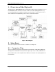
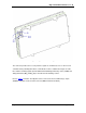
Digi m10 Hardware Reference v 1.20 1. Overview of the Digi m10 The Digi m10 is an ORBCOMM Subscriber Communicator, which enables modem-like access to the ORBCOMM satellite network. It is ideal for machine-to-machine (M2M) applications (e.g. asset tracking, utility meters, pipeline monitoring, etc.) that monitor or control remote assets. It can be added to an existing tracking system or run as a stand-alone modem. Figure 1: Block Diagram 2.
Digi m10 Hardware Reference v 1.20 Figure 2: Digi m10 Pin Numbering The connector provides the necessary interface signals to communicate over a 3.3V TTL level serial link and to power Digi m10. Basic communication can be established using the Tx & Rx lines and the remaining signals provide additional handshaking (RTS/CTS), status (SA/DA) and debug information (Dbg_Tx/Dbg_Rx) as described in the following sections. Refer to Table 1 for details.
Digi m10 Hardware Reference v 1.20 Figure 3: Pin Assignment Table 1: Connector Pins on the Digi m10 Pin Name Description 1 VCC Supply 2 GND Ground 3 VCC Supply 4 GND Ground 5 PWR_EN Digi m10 Power Enable Digital I/O Comments Direction Input 6 GND 7 RX 3.3 V UART Interface. Host controller to the Digi m10 Input 8 TX 3.3V UART Interface. Digi m10 to host controller. Output 9 SA Satellite Available Output 10 DA Data Available Output 11 Dbg_Tx 3.
Digi m10 Hardware Reference v 1.20 2.2 2.2.1 Serial Interface Host Port The host port is the main serial interface and provides device management and monitoring using 3.3 V levels. The serial data is carried on the Transmit (TX) and Receive (RX) lines. The details of the Transmit and Receive pins are shown in Table 2. An RS232 level shifter is required to connect the Digi m10 to a PC. This is already available on the development board, which comes with the Digi m10 JumpStart Kit.
Digi m10 Hardware Reference v 1.20 to the Digi m10 Note: The Dbg_Rx line (Pin 12) needs to be pulled high using a 10KΩ resistor to 3.3V on the Host board even if Debug port is not used. 2.3 Power and Ground The Digi m10 is powered using five pins of its 14-pin connector (see Table 4). The five mounting pins on the shield of the Digi m10 are also connected to the ground plane of the Digi m10. Table 4: Power Pins 2.
Digi m10 Hardware Reference v 1.20 Figure 4: Timing Diagram for Powering Up The delay between PWR_EN going high with respect to VCC going high is not critical. Digi International recommends a 10 milliseconds delay. 2.4.2 Powering Down The host controller can power down the m10 by setting the PWR_EN pin to LOW. The host controller can leave the supply voltage for Digi m10 ON, or remove it at its discretion. If the supply is left ON with PWR_EN set to low, the Digi m10 will be powered down.
Digi m10 Hardware Reference v 1.20 goes low only after the host controller has cleared the outbound (OB) queue. The Digi m10's timing diagram for DA is shown in Figure 6. Table 6: DA Pin Pin 10 Name Description DA Data Available Figure 6: Timing Diagram for Data Available 2.6 RTS/CTS Implementation Hardware flow control is disabled by default. When it is enabled, hardware flow control is implemented using RTS (Request to Send ) and (Clear To Send) signals.
Digi m10 Hardware Reference v 1.20 Figure 7: Timing Diagram for Satellite Available 2.8 RF Interface The RF connector for the Digi m10 (see Figure 8) is an MMCX plug, with an impedance of 50 Ω nominal. Refer to Table 8 for details. Figure 8: RF Connector on the Digi m10 Table 8: RF Interface Details Parameter Value Transmit Power 5 W (37 + / -1 dBm) TX Frequency 148 MHz to 150.
Digi m10 Hardware Reference v 1.20 The Digi m10 is protected from VSWR failure. However, for best performance, Digi International recommends using an antenna with good VSWR readings (see Table 8) at both the RX and TX frequencies. Digi International, Inc.
Digi m10 Hardware Reference v 1.20 3. Technical Specifications This chapter describes the environmental, electrical, and mechanical specifications of the Digi m10. 3.1 Environmental The Digi m10 conforms to the relevant sections of the following documents: 1. ORBCOMM Subscriber Communicator (SC) Standards and Specifications 2. SAE J1455 Joint SAE / TMC Recommended Environmental Practices for Electronic Equipment Design (Heavy-Duty Trucks) 3. FCC Part 2 and Part 25 4.
Digi m10 Hardware Reference v 1.20 Equipment does not have a conducting cable (ex: mains supply, signal line, or ground connection) which can couple the disturbing RF field into the equipment. Exempted from this test as per standard. 3.1.1.4 Conducted Immunity The RF connector on the Digi m10 complies with the test methodology and test levels for conducted immunity defined in EN 300 832. (Refer to Section 4.
Digi m10 Hardware Reference v 1.20 The Digi m10 has been designed and tested to operate under the conditions shown in Table 9 Table 9: Operating Conditions Operating Temperature Humidity Cycle -40 °F to +185 °F (-40 °C to +85 °C) SAE J1455 4.2.3 , Fig 4a , 8h, For 24 hours with a 12 V supply 3 cycles (90% RH) 3.1.4 Comments Storage Temperature The Digi m10 can be stored for extended periods from -58 °F to +185 °F (-50 °C to +85 °C).
Digi m10 Hardware Reference v 1.20 3.2.1 Power Design 3.2.1.1 Power Supply The Digi m10 operates on a single unregulated power source of 9 V to 18 V DC (nominal 12 V) supplied through the pins of the host connector. The Power ON / OFF control circuit is outside the Digi m10 and is controlled by host controller. Low: OFF state High: ON state The Digi m10 does not have reverse polarity protection. Therefore, ensure that only positive voltage is supplied to avoid damaging it. 3.2.1.
Digi m10 Hardware Reference v 1.20 3.2.2 Digital Input / Output Specifications The output pins can source / sink up to 10mA. For higher currents, the outputs must be buffered. Table 10: Digital I/O Electrical Specifications Parameter Min (V) Max (V) VInput Low 0 0.8 Not applicable (NA) VInput High 2.0 3.3 NA VOutput Low 0 0.4 2 mA VOutput High 2.4 3.3 2 mA 3.2.3 Maximum Recommended Load Lifespan 3.2.3.
Digi m10 Hardware Reference v 1.20 Figure 9: Digi m10 Dimensions 3.3.2 Mounting The Digi m10 can be mounted directly to the host PCB using a board-to-board connector. The Digi m10 has five solder legs, which must be soldered to the host controller’s common ground reference plane. The host controller’s PCB needs to have five mounting holes to accommodate the Digi m10.
Digi m10 Hardware Reference v 1.20 4. Approvals and Certifications The Digi m10 satellite modem carries the following certifications and regulatory approvals and certifications: FCC CE Mark C-Tick (Australia/New Zealand) ORBCOMM Type Approval SAE TELEC IC Digi International, Inc.
Digi m10 Hardware Reference v 1.20: 5. Using the Digi m10 This chapter describes the details regarding the functioning of the Digi m10. 5.1 Interfacing with the Digi m10 Figure 10 illustrates how the host controller can be interfaced with the Digi m10. Figure 10: Interface Between the Host Controller and the Digi m10 If Digi m10 is being used, then the UART signals are at TTL levels. Digi International, Inc.
Digi m10 Hardware Reference v 1.20 5.2 The Digi m10 JumpStart Kit The development board (see Figure 11) provides users with an easy way to evaluate the Digi m10. Figure 11: Layout of the Development Board Digi International, Inc.
Digi m10 Hardware Reference v 1.20: The different components of the development board are as follows: SW1: This switch is used to power ON the JumpStart kit, which is indicated by the glowing of red LEDs (Digi m10 POWER ENABLE). SW2: This switch is used to turn m10 ON continuously(PWR_EN connected to 3.3V) or based on DTR signal from the Host RS232/USB Port. Power Jack: A 9 - 18 V supply can be fed through this jack.
Digi m10 Hardware Reference v 1.20 6. Antenna Information 7. Which antenna should be used with the Digi m10? You can find ORBCOMM recommendations at http://www.orbcomm.com/our-partners-antennas.htm. It provides details and comparisons of antennas from different vendors. To know more about the general guidelines for antenna selection and installation when using the ORBCOMM System, refer to the whitepaper A Practical Guide to ORBCOMM Antenna Selection available at http://www.orbcomm.
Digi m10 Hardware Reference v 1.20: Appendix A: Digi m10 Mechanical Drawings Figure 12: Digi m10 Host Board’s Recommended Mechanical Drawing Figure 13: Digi m10 Host Board’s Recommended Mechanical Drawing: Part A Digi International, Inc.
Digi m10 Hardware Reference v 1.20 Figure 14: Digi m10 Host Board’s Recommended Mechanical Drawing: Part B Digi International, Inc.
Digi m10 Hardware Reference v 1.20: Figure 15: Digi m10 Host Board’s Recommended Mechanical Drawing: Part C Digi International, Inc.
Digi m10 Hardware Reference v 1.20 Figure 16: Digi m10 Host Board’s Recommended Mechanical Drawing: Part D Digi International, Inc.
Digi m10 Hardware Reference v 1.20: Appendix B: Development Board Mechanical Drawing Digi International, Inc.
Digi m10 Hardware Reference v 1.20 Appendix C: Digi m10 Development Board Schematic Figure 17: Development Board Schematic Digi International, Inc.
Digi m10 Hardware Reference v 1.20: Figure 18: Development Board Schematic (Part A) Figure 19: Development Board Schematic (Part B) Figure 20: Development Board Schematic (Part C) Digi International, Inc.
Digi m10 Hardware Reference v 1.20 Figure 21: Development Board Schematic (Part D) Digi International, Inc.
Digi m10 Hardware Reference v 1.20: Digi International, Inc.
Digi m10 Hardware Reference v 1.20 Appendix D: m10 Modifications for Industry Canada Compliance In order to be compliant with Industry Canada certifications, Digi recommends that the circuit pictured below be added to the Digi m10 host board. Appendix E: Recommendation for improving emission performance To improve the emission performance, it is recommended to add BLM18AG601SN1 on the m10 interfacing signals. Digi International, Inc.