
International Processor Hardware Reference

TIMING
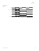
Memory Timing
500 Hardware Reference NS9215
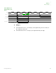
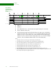
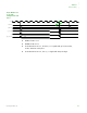
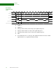
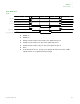
Static write cycle
with configurable
wait states
WTWR = from 0 to 15
WWEN = from 0 to 15
The WTWR field determines the length on the write cycle.
During a 32-bit transfer, all four byte_lane signals will go low.
During a 16-bit transfer, two byte_lane signals will go low.
During an 8-bit transfer, only one byte_lane signal will go low.
Notes:
1 Timing of the st_cs_n signal is determined with a combination of the WTWR and WWEN fields. The
st_cs_n signal will always go low at least one clock before we_n goes low, and will go high one clock
after we_n goes high.
2 Timing of the we_n signal is determined with a combination of the WTWR and WWEN fields.
3 Timing of the byte_lane signals is determined with a combination of the WTWR and WWEN fields. The
byte_lane signals will always go low one clock before we_n goes low, and will go one clock high after we_n goes
high.
4 If the PB field is set to 0, the byte_lane signals will function as the write enable signals and the we_n signal will
always be high.
5 If the PB field is set to 0, the timing for the byte_lane signals is set with the WTWR and WWEN fields.
M22M21
M24M23
M22M21
M20M19
M18M17
M16M15
Note-2
Note-3
Note-5Note-4
Note-1
clk_out
data <31:0>
ad dr<17:0>
st_cs_ n<3: 0>
we_n
byte_lan e< 3: 0>
byte_lan e[ 3:0 ] as WE *