RabbitCore RCM4000 C-Programmable Analog Core Module with Ethernet User’s Manual 019–0157 • 060501–A
RabbitCore RCM4000 User’s Manual Part Number 019-0157 • 060501–A • Printed in U.S.A. ©2006 Rabbit Semiconductor • All rights reserved. Rabbit Semiconductor reserves the right to make changes and improvements to its products without providing notice. Trademarks Rabbit and Dynamic C are registered trademarks of Rabbit Semiconductor. Rabbit 4000 and RabbitCore are trademarks of Rabbit Semiconductor.
TABLE OF CONTENTS Chapter 1. Introduction 1 1.1 RCM4000 Features ...............................................................................................................................2 1.2 Advantages of the RCM4000 ...............................................................................................................3 1.3 Development and Evaluation Tools......................................................................................................4 1.3.1 RCM4000 Development Kit ..
.5 Other Hardware .................................................................................................................................. 38 4.5.1 Clock Doubler ............................................................................................................................ 38 4.5.2 Spectrum Spreader...................................................................................................................... 38 4.6 Memory .......................................................
B.4.4 Serial Communication ..............................................................................................................103 B.4.4.1 RS-232 ............................................................................................................................. 104 B.5 Prototyping Board Jumper Configurations ......................................................................................105 Appendix C. Power Supply 109 C.1 Power Supplies..........................................
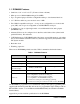
RabbitCore RCM4100
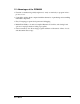
1. INTRODUCTION The RCM4000 series of RabbitCore modules is one of the next generation of core modules that take advantage of new Rabbit® 4000 features such as hardware DMA, clock speeds of up to 60 MHz, I/O lines shared with up to five serial ports and four levels of alternate pin functions that include variable-phase PWM, auxiliary I/O, quadrature decoder, and input capture.
1.1 RCM4000 Features • Small size: 1.84" × 2.42" × 0.77" (47 mm × 61 mm × 20 mm) • Microprocessor: Rabbit 4000 running at 58.98 MHz • Up to 29 general-purpose I/O lines configurable with up to four alternate functions • 3.3 V I/O lines with low-power modes down to 2 kHz • Five CMOS-compatible serial ports — four ports are configurable as a clocked serial ports (SPI), and one port is configurable as an SDLC/HDLC serial port.
1.2 Advantages of the RCM4000 • Fast time to market using a fully engineered, “ready-to-run/ready-to-program” microprocessor core. • Competitive pricing when compared with the alternative of purchasing and assembling individual components. • Easy C-language program development and debugging • Rabbit Field Utility to download compiled Dynamic C .bin files, and cloning board options for rapid production loading of programs.
1.3 Development and Evaluation Tools 1.3.1 RCM4000 Development Kit The RCM4000 Development Kit contains the hardware essentials you will need to use your RCM4000 module. The items in the Development Kit and their use are as follows. • RCM4010 module. • Prototyping Board. • AC adapter, 12 V DC, 1 A. (Included only with Development Kits sold for the North American market.
1.3.2 Software The RCM4000 is programmed using version 10.03 or later of Dynamic C. A compatible version is included on the Development Kit CD-ROM. Rabbit Semiconductor also offers add-on Dynamic C modules containing the popular µC/OS-II real-time operating system, as well as PPP, Advanced Encryption Standard (AES), and other select libraries. In addition to the Web-based technical support included at no extra charge, a one-year telephone-based technical support module is also available for purchase.
6 RabbitCore RCM4000
2. GETTING STARTED This chapter describes the RCM4000 hardware in more detail, and explains how to set up and use the accompanying Prototyping Board. NOTE: This chapter (and this manual) assume that you have the RCM4000 Development Kit. If you purchased an RCM4000 module by itself, you will have to adapt the information in this chapter and elsewhere to your test and development setup. 2.
2.2 Hardware Connections There are three steps to connecting the Prototyping Board for use with Dynamic C and the sample programs: 1. Prepare the Prototyping Board for Development. 2. Attach the RCM4000 module to the Prototyping Board. 3. Connect the programming cable between the RCM4000 and the PC. 4. Connect the power supply to the Prototyping Board. 2.2.
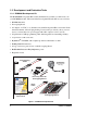
2.2.2 Attach Module to Prototyping Board Turn the RCM4000 module so that the mounting holes line up with the corresponding holes on the Prototyping Board. Insert a standoff between the upper mounting hole and the Prototyping Board as shown, then insert the module’s header J3 on the bottom side into socket RCM1 on the Prototyping Board.
2.2.3 Connect Programming Cable The programming cable connects the module to the PC running Dynamic C to download programs and to monitor the module during debugging. Connect the 10-pin connector of the programming cable labeled PROG to header J1 on the RCM4000 as shown in Figure 4. Be sure to orient the marked (usually red) edge of the cable towards pin 1 of the connector. (Do not use the DIAG connector, which is used for a normal serial connection.
2.2.4 Connect Power Once all the other connections have been made, you can connect power to the Prototyping Board. Connect the AC adapter to 3-pin header J1 on the Prototyping Board as shown in Figure 4 above. The connector may be attached either way as long as it is not offset to one side—the center pin of J1 is always connected to the positive terminal, and either edge pin is ground. Plug in the AC adapter. The PWR LED on the Prototyping Board next to the power connector at J1 should light up.
2.3 Run a Sample Program If you already have Dynamic C installed, you are now ready to test your programming connections by running a sample program. Start Dynamic C by double-clicking on the Dynamic C icon or by double-clicking on dcrab_XXXX.exe in the Dynamic C root directory, where XXXX are version-specific characters. If you are using a USB port to connect your computer to the RCM4000, choose Options > Project Options and select “Use USB to Serial Converter” under the Communications tab.
2.4 Where Do I Go From Here? If the sample program ran fine, you are now ready to go on to the sample programs in Chapter 3 and to develop your own applications. The sample programs can be easily modified for your own use. The user's manual also provides complete hardware reference information and software function calls for the RCM4000 and the Prototyping Board. For advanced development topics, refer to the Dynamic C User’s Manual, also in the online documentation set. 2.4.
14 RabbitCore RCM4000
3. RUNNING SAMPLE PROGRAMS To develop and debug programs for the RCM4000 (and for all other Z-World and Rabbit Semiconductor hardware), you must install and use Dynamic C. This chapter provides a tour of its major features with respect to the RCM4000. 3.1 Introduction To help familiarize you with the RCM4000 modules, Dynamic C includes several sample programs.
3.2 Sample Programs Of the many sample programs included with Dynamic C, several are specific to the RCM4000 modules. These programs will be found in the SAMPLES\RCM4000 folder. • CONTROLLED.C—Demonstrates use of the digital outputs by having you turn LEDs DS2 and DS3 on the Prototyping Board on or off from the STDIO window on your PC. Parallel Port B bit 2 = LED DS2 Parallel Port B bit 3 = LED DS3 Once you compile and run CONTROLLED.C, the following display will appear in the Dynamic C STDIO window.
• LOW_POWER.C—demonstrates how to implement a function in RAM to reduce power consumption by the Rabbit microprocessor. There are four features that lead to the lowest possible power draw by the microprocessor. 1. Run the CPU from the 32 kHz crystal. 2. Turn off the high-frequency crystal oscillator. 3. Run from RAM. 4. Ensure that internal I/O instructions do not use CS0. Once you are ready to compile and run this sample program, use instead of just F9.
3.2.1 Use of NAND Flash (RCM4000 only) The following sample programs can be found in the SAMPLES\RCM4000\NANDFlash folder. • NFLASH_DUMP.c—This program is a utility for dumping the nonerased contents of a NAND flash chip to the Dynamic C STDIO window, and the contents may be redirected to a serial port. When the sample program starts running, it attempts to communicate with the userselected NAND flash chip.
Follow these instructions to set up your PC or notebook. Check with your administrator if you are unable to change the settings as described here since you may need administrator privileges. The instructions are specifically for Windows 2000, but the interface is similar for other versions of Windows. TIP: If you are using a PC that is already on a network, you will disconnect the PC from that network to run these sample programs.
3.2.2 Serial Communication The following sample programs are found in the SAMPLES\RCM4000\SERIAL folder. • FLOWCONTROL.C—This program demonstrates how to configure Serial Port D for CTS/RTS with serial data coming from Serial Port C (TxC) at 115,200 bps. The serial data received are displayed in the STDIO window.
• SIMPLE5WIRE.C—This program demonstrates 5-wire RS-232 serial communication with flow control on Serial Port D and data flow on Serial Port C. To set up the Prototyping Board, you will need to tie TxD and RxD together on the RS-232 header at J4, and you will also tie TxC and RxC together using the jumpers supplied in the Development Kit as shown in the diagram.
3.2.3 A/D Converter Inputs (RCM4000 only) The following sample programs are found in the SAMPLES\RCM4000\ADC folder. • AD_CAL_CHAN.C—Demonstrates how to recalibrate one single-ended analog input channel with one gain using two known voltages to generate the calibration constants for that channel. The constants will be rewritten into the user block data area. Connect a positive voltage to an analog input channel on the Prototyping Board, and connect the ground to GND.
4. HARDWARE REFERENCE Chapter 4 describes the hardware components and principal hardware subsystems of the RCM4000. Appendix A, “RCM4000 Specifications,” provides complete physical and electrical specifications. Figure 5 shows the Rabbit-based subsystems designed into the RCM4000. Ethernet SRAM Program Flash 32 kHz 44.
4.1 RCM4000 Digital Inputs and Outputs Figure 6 shows the RCM4000 pinouts for header J3. J3 +3.3 V_IN /RESET_OUT /IOWR VBAT_EXT PA1 PA3 PA5 PA7 PB1 PB3 PB5 PB7 PC1 PC3 PC5 PC7 PE1 PE3 PE5/SMODE0 PE7/STATUS LN1 LN3 LN5 LN7 n.c./VREF GND /IORD /RESET_IN PA0 PA2 PA4 PA6 PB0 PB2 PB4 PB6 PC0 PC2 PC4 PC6 PE0 PE2 PE4 PE6/SMODE1 LN0 LN2 LN4 LN6 CONVERT GND n.c. = not connected Note: These pinouts are as seen on the Bottom Side of the module. Figure 6.
Figure 7 shows the use of the Rabbit 3000 microprocessor ports in the RCM4000 modules. PC0, PC2 PC1, PC3 PA0PA7 PB2PB7 PD0PD7 Port A Port B Port D Port C RABBIT® Port E (Serial Ports C & D) Serial Ports E & F PB1, PC6 PC7, /RES PC4* PC5* * PC4 and PC5 are not available on RCM4100 module. Programming Port (Serial Port A) A/D Converter (Serial Port B) RAM PE0PE7 4000 Real-Time Clock Watchdog 11 Timers Slave Port Clock Doubler Backup Battery Support /RES_IN /IORD Misc.
Table 2. RCM4000 Pinout Configurations Pin Pin Name Default Use Alternate Use Notes 1 +3.
Table 2.
Table 2.
Table 2. RCM4000 Pinout Configurations (continued) Pin Pin Name Default Use Alternate Use Notes 40–47 LN[0:7] Analog Input 48 CONVERT Analog Input 49 VREF Analog reference voltage 1.15 V/2.048 V/2.500 V on-chip ref. voltage (RCM4000 only) 50 GND Ground Analog ground A/D converter (RCM4000 only) 4.1.1 Memory I/O Interface The Rabbit 4000 address lines (A0–A19) and all the data lines (D0–D7) are routed internally to the onboard flash memory and SRAM chips.
4.2 Serial Communication The RCM4000 module does not have any serial transceivers directly on the board. However, a serial interface may be incorporated on the board the RCM4000 is mounted on. For example, the Prototyping Board has an RS-232 transceiver chip. 4.2.1 Serial Ports There are five serial ports designated as Serial Ports A, B, C, D, and F. All five serial ports can operate in an asynchronous mode up to the baud rate of the system clock divided by 8.
4.2.2 Ethernet Port Figure 8 shows the pinout for the RJ-45 Ethernet port (J2). Note that some Ethernet connectors are numbered in reverse to the order used here. ETHERNET 1 8 1. 2. 3. 6. RJ-45 Plug E_Tx+ E_Tx E_Rx+ E_Rx RJ-45 Jack Figure 8. RJ-45 Ethernet Port Pinout Two LEDs are placed next to the RJ-45 Ethernet jack, one to indicate an Ethernet link (LINK) and one to indicate Ethernet activity (ACT). The RJ-45 connector is shielded to minimize EMI effects to/from the Ethernet signals.
4.2.3 Programming Port The RCM4000 is programmed via the 10-pin header labeled J1. The programming port uses the Rabbit 4000’s Serial Port A for communication. Dynamic C uses the programming port to download and debug programs. Serial Port A is also used for the following operations. • Cold-boot the Rabbit 4000 on the RCM4000 after a reset. • Remotely download and debug a program over an Ethernet connection using the RabbitLink EG2110.
4.3 Programming Cable The programming cable is used to connect the programming port of the RCM4000 to a PC serial COM port. The programming cable converts the RS-232 voltage levels used by the PC serial port to the CMOS voltage levels used by the Rabbit 4000. When the PROG connector on the programming cable is connected to the programming port on the RCM4000, programs can be downloaded and debugged over the serial interface.
A program “runs” in either mode, but can only be downloaded and debugged when the RCM4000 is in the Program Mode. Refer to the Rabbit 4000 Microprocessor User’s Manual for more information on the programming port. 4.3.2 Standalone Operation of the RCM4000 Once the RCM4000 has been programmed successfully, remove the programming cable from the programming connector and reset the RCM4000. The RCM4000 may be reset by removing, then reapplying power, or by pressing the RESET button on the Prototyping Board.
4.4 A/D Converter (RCM4000 only) The RCM4000 has an onboard ADS7870 A/D converter whose scaling and filtering are done via the motherboard on which the RCM4000 module is mounted. The A/D converter multiplexes converted signals from eight single-ended or four differential inputs to Serial Port B on the Rabbit 4000. The eight analog input pins, LN0–LN7, each have an input impedance of 6–7 MΩ, depending on whether they are used as single-ended or differential inputs.
If a device such as a battery is connected across two channels R5 AIN0 for a differential measurement, LN0 ADC and it is not referenced to 2.2 nF R13 Device + analog ground, then the current I + from the device will flow 2.2 nF R14 through both sets of attenuator R6 AIN1 resistors as shown in Figure 11. LN1 This will generate a negative voltage at one of the inputs, Figure 11. Current Flow from Ungrounded LN1, which will almost ceror Floating Source tainly lead to inaccurate A/D conversions.
4.4.1 A/D Converter Power Supply The analog section is isolated from digital noise generated by other components by way of a low-pass filter composed of C1, L1, and C3 on the RCM4000 as shown in Figure 13. The +V analog power supply powers the A/D converter chip. +3.3 V +V L1 C1 2.2 nF C3 100 nF Figure 13.
4.5 Other Hardware 4.5.1 Clock Doubler The RCM4000 takes advantage of the Rabbit 4000 microprocessor’s internal clock doubler. A built-in clock doubler allows half-frequency crystals to be used to reduce radiated emissions. The 58.98 MHz frequency specified for the RCM4000 is generated using a 29.49 MHz crystal. The clock doubler may be disabled if 58.98 MHz clock speeds are not required.
4.6 Memory 4.6.1 SRAM RCM4000 modules have 512K of data SRAM installed at U16. 4.6.2 Flash EPROM All RCM4000 modules also have 512K of flash EPROM installed at U3. NOTE: Rabbit Semiconductor recommends that any customer applications should not be constrained by the sector size of the flash EPROM since it may be necessary to change the sector size in the future. Writing to arbitrary flash memory addresses at run time is discouraged. Instead, define a “user block” area to store persistent data.
40 RabbitCore RCM4000
5. SOFTWARE REFERENCE Dynamic C is an integrated development system for writing embedded software. It runs on an IBM-compatible PC and is designed for use with single-board computers and other devices based on the Rabbit microprocessor. Chapter 5 describes the libraries and function calls related to the RCM4000. 5.1 More About Dynamic C Dynamic C has been in use worldwide since 1989. It is specially designed for programming embedded systems, and features quick compile and interactive debugging.
Dynamic C has a number of standard features. • Full-feature source and/or assembly-level debugger, no in-circuit emulator required. • Royalty-free TCP/IP stack with source code and most common protocols. • Hundreds of functions in source-code libraries and sample programs: X Exceptionally fast support for floating-point arithmetic and transcendental functions. X RS-232 and RS-485 serial communication. X Analog and digital I/O drivers. X I2C, SPI, GPS, file system. X LCD display and keypad drivers.
5.2 Dynamic C Function Calls 5.2.1 Digital I/O The RCM4000 was designed to interface with other systems, and so there are no drivers written specifically for the I/O. The general Dynamic C read and write functions allow you to customize the parallel I/O to meet your specific needs. For example, use WrPortI(PEDDR, &PEDDRShadow, 0x00); to set all the Port E bits as inputs, or use WrPortI(PEDDR, &PEDDRShadow, 0xFF); to set all the Port E bits as outputs.
The sample code below shows how a protected variable is defined and how its value can be restored. main() { protected int state1, state2, state3; ... _sysIsSoftReset(); // restore any protected variables The bbram keyword may also be used instead if there is a need to store a variable in battery-backed SRAM without affecting the performance of the application program. Data integrity is not assured when a reset or power failure occurs during the update process.
5.2.4 Prototyping Board Functions The functions described in this section are for use with the Prototyping Board features. The source code is in the Dynamic C LIB\RCM4xxx\RCM40xx.LIB library if you need to modify it for your own board design. NOTE: The analog input function calls are supported only by the RCM4000 model since the RCM4010 does not have an A/D converter. Other generic functions applicable to all devices based on Rabbit microprocessors are described in the Dynamic C Function Reference Manual.
5.2.4.2 Alerts void timedAlert(unsigned long timeout); Polls the real-time clock until a timeout occurs. The RCM4000 will be in a low-power mode during this time. Once the timeout occurs, this function call will enable the normal power source. The A/D converter oscillator will be disabled and enabled. PARAMETERS timeout is the duration of the timeout in seconds RETURN VALUE None.
5.2.5 Analog Inputs (RCM4000 only) unsigned int anaInConfig(unsigned int instructionbyte, unsigned int cmd, long baud); Use this function to configure the A/D converter. This function will address the A/D converter in Register Mode only, and will return an error if you try the Direct Mode. Appendix B.4.3 provides additional addressing and command information.
PARAMETERS instructionbyte is the instruction byte that will initiate a read or write operation at 8 or 16 bits on the designated register address. For example, checkid = anaInConfig(0x5F, 0, 9600); // read ID and set baud rate cmd are the command data that configure the registers addressed by the instruction byte. Enter 0 if you are performing a read operation. For example, i = anaInConfig(0x07, 0x3b, 0); // write ref/osc reg and enable baud is the serial clock transfer rate of 9600 to 57,600 bps.
unsigned int anaInDriver(unsigned int cmd, unsigned int len); Reads the voltage of an analog input channel by serial-clocking an 8-bit command to the A/D converter by its Direct Mode method. This function assumes that Mode1 (most significant byte first) and the A/D converter oscillator have been enabled. See anaInConfig() for the setup. The conversion begins immediately after the last data bit has been transferred. An exception error will occur if Direct Mode bit D7 is not set.
RETURN VALUE A value corresponding to the voltage on the analog input channel: 0–2047 for 11-bit conversions (bit 12 for sign) -1 overflow or out of range -2 conversion incomplete, busy bit timeout SEE ALSO anaInConfig, anaIn, brdInit 50 RabbitCore RCM4000
unsigned int anaIn(unsigned int channel, int opmode, int gaincode); Reads the value of an analog input channel using the Direct Mode method of addressing the A/D converter. Note that it takes about 1 second to ensure an internal capacitor on the A/D converter is charged when the function is called the first time.
int anaInCalib(int channel, int opmode, int gaincode, int value1, float volts1, int value2, float volts2); Calibrates the response of the desired A/D converter channel as a linear function using the two conversion points provided. Four values are calculated and placed into global tables _adcCalibS, _adcCalibD, and adcCalibM to be later stored into simulated EEPROM using the function anaInEEWr(). Each channel will have a linear constant and a voltage offset.
value1 is the first A/D converter channel raw count value volts1 is the voltage or current corresponding to the first A/D converter channel value (0 to +20 V or 4 to 20 mA) value2 is the second A/D converter channel raw count value volts2 is the voltage or current corresponding to the first A/D converter channel value (0 to +20 V or 4 to 20 mA) RETURN VALUE 0 if successful. -1 if not able to make calibration constants.
float anaInVolts(unsigned int channel, unsigned int gaincode); Reads the state of a single-ended analog input channel and uses the previously set calibration constants to convert it to volts. PARAMETERS channel is the channel number (0 to 7) corresponding to LN0_IN to LN7_IN Channel Code Single-Ended Input Lines* Voltage Range† (V) 0 +AIN0 0–22.5 1 +AIN1 0–22.5 2 +AIN2 0–22.5 3 +AIN3 0–22.5 4 +AIN4 0–22.5 5 +AIN5 0–22.5 6 +AIN6 0–22.5 7 +AIN7 0–2‡ * Negative input is ground.
float anaInDiff(unsigned int channel, unsigned int gaincode); Reads the state of differential analog input channels and uses the previously set calibration constants to convert it to volts. PARAMETERS channel is the analog input channel number (0 to 7) corresponding to LN0_IN to LN7_IN channel DIFF Voltage Range (V) 0 +AIN0 -AIN1 -22.5 to +22.5* 1 +AIN1 -AIN1 — 2 +AIN2 -AIN3 -22.5 to +22.5* 3 +AIN3 -AIN3 — 4 +AIN4 -AIN5 -22.5 to +22.
float anaInmAmps(unsigned int channel); Reads the state of an analog input channel and uses the previously set calibration constants to convert it to current. PARAMETERS channel is the channel number (0–7): Channel Code 4–20 mA Input Lines* 0 +AIN0 1 +AIN1 2 +AIN2 3 +AIN3† 4 +AIN4* 5 +AIN5* 6 +AIN6* 7 +AIN7 * Negative input is ground. † Applies to Prototyping Board. RETURN VALUE A current value between 4.00 and 20.00 mA corresponding to the current on the analog input channel.
root int anaInEERd(unsigned int channel, unsigned int opmode, unsigned int gaincode); Reads the calibration constants, gain, and offset for an input based on their designated position in the flash memory, and places them into global tables _adcCalibS, _adcCalibD, and _adcCalibM for analog inputs. Depending on the flash size, the following macros can be used to identify the starting address for these locations.
gaincode is the gain code of 0 to 7. The gaincode parameter is ignored when channel is ALLCHAN. Gain Code Voltage Range* (V) 0 0–22.5 1 0–11.25 2 0–5.6 3 0–4.5 4 0–2.8 5 0–2.25 6 0–1.41 7 0–1.126 * Applies to Prototyping Board. RETURN VALUE 0 if successful. -1 if address is invalid or out of range.
int anaInEEWr(unsigned int channel, int opmode unsigned int gaincode); Writes the calibration constants, gain, and offset for an input based from global tables _adcCalibS, _adcCalibD, and _adcCalibM to designated positions in the flash memory. Depending on the flash size, the following macros can be used to identify the starting address for these locations.
gaincode is the gain code of 0 to 7. The gaincode parameter is ignored when channel is ALLCHAN. Gain Code Voltage Range* (V) 0 0–22.5 1 0–11.25 2 0–5.6 3 0–4.5 4 0–2.8 5 0–2.25 6 0–1.41 7 0–1.126 * Applies to Prototyping Board. RETURN VALUE 0 if successful -1 if address is invalid or out of range.
5.3 Upgrading Dynamic C Dynamic C patches that focus on bug fixes are available from time to time. Check the Web sites • www.zworld.com/support/ or • www.rabbitsemiconductor.com/support/ for the latest patches, workarounds, and bug fixes. 5.3.1 Add-On Modules Dynamic C installations are designed for use with the board they are included with, and are included at no charge as part of our low-cost kits.
62 RabbitCore RCM4000
6. USING THE TCP/IP FEATURES 6.1 TCP/IP Connections Programming and development can be done with the RCM4000 without connecting the Ethernet port to a network. However, if you will be running the sample programs that use the Ethernet capability or will be doing Ethernet-enabled development, you should connect the RCM4000 module’s Ethernet port at this time. Before proceeding you will need to have the following items.
1. Connect the AC adapter and the serial programming cable as shown in Chapter 2, “Getting Started.” 2. Ethernet Connections There are four options for connecting the RCM4000 module to a network for development and runtime purposes. The first two options permit total freedom of action in selecting network addresses and use of the “network,” as no action can interfere with other users. We recommend one of these options for initial development. • No LAN — The simplest alternative for desktop development.
6.2 TCP/IP Primer on IP Addresses Obtaining IP addresses to interact over an existing, operating, network can involve a number of complications, and must usually be done with cooperation from your ISP and/or network systems administrator. For this reason, it is suggested that the user begin instead by using a direct connection between a PC and the RCM4000 using an Ethernet crossover cable or a simple arrangement with a hub. (A crossover cable should not be confused with regular straight through cables.
Hub(s) T1 in Adapter Ethernet Firewall Proxy Server Network Ethernet Typical Corporate Network RCM4000 System If your system administrator can give you an Ethernet cable along with its IP address, the netmask and the gateway address, then you may be able to run the sample programs without having to setup a direct connection between your computer and the RCM4000.
6.2.1 IP Addresses Explained IP (Internet Protocol) addresses are expressed as 4 decimal numbers separated by periods, for example: 216.103.126.155 10.1.1.6 Each decimal number must be between 0 and 255. The total IP address is a 32-bit number consisting of the 4 bytes expressed as shown above. A local network uses a group of adjacent IP addresses. There are always 2N IP addresses in a local network. The netmask (also called subnet mask) determines how many IP addresses belong to the local network.
6.2.2 How IP Addresses are Used The actual hardware connection via an Ethernet uses Ethernet adapter addresses (also called MAC addresses). These are 48-bit addresses and are unique for every Ethernet adapter manufactured. In order to send a packet to another computer, given the IP address of the other computer, it is first determined if the packet needs to be sent directly to the other computer or to the gateway.
6.2.3 Dynamically Assigned Internet Addresses In many instances, devices on a network do not have fixed IP addresses. This is the case when, for example, you are assigned an IP address dynamically by your dial-up Internet service provider (ISP) or when you have a device that provides your IP addresses using the Dynamic Host Configuration Protocol (DHCP).
6.3 Placing Your Device on the Network In many corporate settings, users are isolated from the Internet by a firewall and/or a proxy server. These devices attempt to secure the company from unauthorized network traffic, and usually work by disallowing traffic that did not originate from inside the network. If you want users on the Internet to communicate with your RCM4000, you have several options.
6.4 Running TCP/IP Sample Programs We have provided a number of sample programs demonstrating various uses of TCP/IP for networking embedded systems. These programs require you to connect your PC and the RCM4000 module together on the same network. This network can be a local private network (preferred for initial experimentation and debugging), or a connection via the Internet.
6.4.1 How to Set IP Addresses in the Sample Programs With the introduction of Dynamic C 7.30 we have taken steps to make it easier to run many of our sample programs. You will see a TCPCONFIG macro. This macro tells Dynamic C to select your configuration from a list of default configurations. You will have three choices when you encounter a sample program with the TCPCONFIG macro. 1.
6.4.2 How to Set Up your Computer for Direct Connect Follow these instructions to set up your PC or notebook. Check with your administrator if you are unable to change the settings as described here since you may need administrator privileges. The instructions are specifically for Windows 2000, but the interface is similar for other versions of Windows. TIP: If you are using a PC that is already on a network, you will disconnect the PC from that network to run these sample programs.
6.5 Run the PINGME.C Sample Program Connect the crossover cable from your computer’s Ethernet port to the RCM4000 module’s RJ-45 Ethernet connector. Open this sample program from the SAMPLES\TCPIP\ ICMP folder, compile the program, and start it running under Dynamic C. The crossover cable is connected from your computer’s Ethernet adapter to the RCM4000 module’s RJ45 Ethernet connector.
6.7 Where Do I Go From Here? NOTE: If you purchased your RCM4000 through a distributor or through a Rabbit Semiconductor or Z-World partner, contact the distributor or partner first for technical support. If there are any problems at this point: • Use the Dynamic C Help menu to get further assistance with Dynamic C. • Check the Rabbit Semiconductor/Z-World Technical Bulletin Board at www.rabbit.com/support/bb/. • Use the Technical Support e-mail form at www.rabbit.com/support/.
76 RabbitCore RCM4000
APPENDIX A. RCM4000 SPECIFICATIONS Appendix A provides the specifications for the RCM4000, and describes the conformal coating.
A.1 Electrical and Mechanical Characteristics Figure A-1 shows the mechanical dimensions for the RCM4000. 1.84 (47) Y2 C66 C54 R47 Y3 C51 C52 C48 C50 (15.7) 0.62 0.72 (16) 0.10 (2.5) (5.8) (2.8) (20) (5.8) 0.23 (2.8) 0.11 (47) (1.6) 1.84 0.064 J3 0.77 (12) 0.47 (61) 0.23 2.42 0.11 (1.6) 0.064 (20) 0.77 (12) 0.47 (18) (28) (9.4) 0.37 R20 L3 1.10 C16 C11 R2 C7 C9 C14 C12 R4 L2 L5 R7 R6 C8 L7 L6 R34 C15 L4 J1 (61) 0.619 C10 R51 R5 C13 R1 2.
It is recommended that you allow for an “exclusion zone” of 0.04" (1 mm) around the RCM4000 in all directions when the RCM4000 is incorporated into an assembly that includes other printed circuit boards. An “exclusion zone” of 0.08" (2 mm) is recommended below the RCM4000 when the RCM4000 is plugged into another assembly. Figure A-2 shows this “exclusion zone.” 2.50 (2) 0.08 (16) 0.51 (63) 2.42 (61) Exclusion Zone 1.92 (2) 0.08 (16) 0.51 (49) J3 1.84 (47) Figure A-2.
Table A-1 lists the electrical, mechanical, and environmental specifications for the RCM4000. Table A-1. RCM4000 Specifications Parameter RCM4000 RCM4010 Rabbit® 4000 at 58.
Table A-1.
A.1.1 A/D Converter Table A-2 shows some of the important A/D converter specifications. For more details, refer to the ADC7870 data sheet. Table A-2. A/D Converter Specifications Parameter Test Conditions Analog Input Characteristics Input Capacitance Input Impedance Common-Mode Differential Mode 6 MΩ 7 MΩ 11 bits 12 bits ±1 LSB ±0.5 LSB Dynamic Characteristics Throughput Rate 82 Max 4 – 9.
A.1.2 Headers The RCM4000 uses a header at J3 for physical connection to other boards. J3 is a 2 × 25 SMT header with a 1.27 mm pin spacing. J1, the programming port, is a 2 × 5 header with a 1.27 mm pin spacing. Figure A-3 shows the layout of another board for the RCM4000 to be plugged into. These reference design values are relative to one of the mounting holes. J1 0.875 (22.2) 0.050 (1.27) J3 RCM4000 Series Footprint 0.284 (7.2) 0.334 (8.5) Figure A-3.
A.2 Rabbit 4000 DC Characteristics Table A-3. Rabbit 4000 Absolute Maximum Ratings Symbol Parameter Maximum Rating TA Operating Temperature -40° to +85°C TS Storage Temperature -55° to +125°C VIH Maximum Input Voltage VDDIO + 0.3 V (max. 3.6 V) VDDIO Maximum Operating Voltage 3.6 V Stresses beyond those listed in Table A-3 may cause permanent damage.
A.3 I/O Buffer Sourcing and Sinking Limit Unless otherwise specified, the Rabbit I/O buffers are capable of sourcing and sinking 8 mA of current per pin at full AC switching speed. Full AC switching assumes a 29.4 MHz CPU clock with the clock doubler enabled and capacitive loading on address and data lines of less than 70 pF per pin. The absolute maximum operating voltage on all I/O is 3.6 V. A.4 Bus Loading You must pay careful attention to bus loading when designing an interface to the RCM4000.
Figure A-4 shows a typical timing diagram for the Rabbit 4000 microprocessor external I/O read and write cycles. External I/O Read (no extra wait states) T1 Tw T2 CLK A[15:0] valid Tadr /CSx /IOCSx TCSx TCSx TIOCSx TIOCSx /IORD TIORD TIORD /BUFEN TBUFEN Tsetup TBUFEN D[7:0] valid Thold External I/O Write (no extra wait states) T1 Tw T2 CLK A[15:0] valid Tadr /CSx /IOCSx /IOWR /BUFEN D[7:0] TCSx TCSx TIOCSx TIOCSx TIOWR TIOWR TBUFEN TBUFEN valid TDHZV TDVHZ Figure A-4.
Table A-8 lists the delays in gross memory access time for several values of VDDIO. Table A-8. Preliminary Data and Clock Delays Clock to Address Output Delay (ns) VDDIO (V) 30 pF 60 pF 90 pF Worst-Case Spectrum Spreader Delay (ns) Data Setup Time Delay (ns) 0.5 ns setting 1 ns setting no dbl / dbl no dbl / dbl 2 ns setting no dbl / dbl 3.3 6 8 11 1 2.3 / 2.3 3 / 4.5 4.5 / 9 1.8 18 24 33 3 7 / 6.
A.5 Conformal Coating The areas around the 32 kHz real-time clock crystal oscillator have had the Dow Corning silicone-based 1-2620 conformal coating applied. The conformally coated area is shown in Figure A-5. The conformal coating protects these high-impedance circuits from the effects of moisture and contaminants over time.
A.6 Jumper Configurations Figure A-6 shows the header locations used to configure the various RCM4000 options via jumpers. RCM4000 Top Side JP1 JP2 JP3 JP4 Figure A-6. Location of RCM4000 Configurable Positions Table A-9 lists the configuration options. Table A-9.
90 RabbitCore RCM4000
APPENDIX B. PROTOTYPING BOARD Appendix B describes the features and accessories of the Prototyping Board, and explains the use of the Prototyping Board to demonstrate the RCM4000 and to build prototypes of your own circuits. The Prototyping Board has power-supply connections and also provides some basic I/O peripherals (RS-232, LEDs, and switches), as well as a prototyping area for more advanced hardware development.
B.1 Introduction The Prototyping Board included in the Development Kit makes it easy to connect an RCM4000 module to a power supply and a PC workstation for development. It also provides some basic I/O peripherals (RS-232, LEDs, and switches), as well as a prototyping area for more advanced hardware development. For the most basic level of evaluation and development, the Prototyping Board can be used without modification.
B.1.1 Prototyping Board Features • Power Connection—A a 3-pin header is provided for connection to the power supply. Note that the 3-pin header is symmetrical, with both outer pins connected to ground and the center pin connected to the raw V+ input. The cable of the AC adapter provided with the North American version of the Development Kit is terminated with a header plug that connects to the 3-pin header in either orientation.
• Current Measurement Option—You may cut the trace below header JP1 on the bottom side of the Prototyping Board and install a 1 × 2 header strip from the Development Kit to allow you to use an ammeter across the pins to measure the current drawn from the +5 V supply. Similarly, you may cut the trace below header JP2 on the bottom side of the Prototyping Board and install a 1 × 2 header strip from the Development Kit to allow you to use an ammeter across the pins to measure the current drawn from the +3.
B.2 Mechanical Dimensions and Layout Figure B-2 shows the mechanical dimensions and layout for the Prototyping Board. 2.735 (6) 0.24 (69.5) 1.935 (3.8) 0.15 (49.1) PWR J1 R2 PB4 PB5 PB6 PB7 PC0 PC1 PC2 PC3 PC4 PC5 PC6 PC7 PE0 PE1 PE2 PE3 R19 PE5 R9 PE7 PE4 PD1 LN1 PD2 LN2 PD4 LN4 PD6 LN6 UX29 J4 GND UX12 RX85 PD0 LN0 AGND DS2 JP25 RX79 DS3 R23 R21 R22 1 S2 UX16 R24 1 S3 GND GND (3.8) (3.8) (4.2) (9.1) GND 0.15 0.165 0.36 0.
Table B-1 lists the electrical, mechanical, and environmental specifications for the Prototyping Board. Table B-1. Prototyping Board Specifications Parameter Specification Board Size 3.80" × 3.80" × 0.48" (97 mm × 97 mm × 12 mm) Operating Temperature 0°C to +70°C Humidity 5% to 95%, noncondensing Input Voltage 8 V to 24 V DC Maximum Current Draw 800 mA max. for +3.3 V supply, (including user-added circuits) 1 A total +3.3 V and +5 V combined Prototyping Area 1.3" × 2.
B.4 Using the Prototyping Board The Prototyping Board is actually both a demonstration board and a prototyping board. As a demonstration board, it can be used to demonstrate the functionality of the RCM4000 right out of the box without any modifications to either board. The Prototyping Board comes with the basic components necessary to demonstrate the operation of the RCM4000.
Selected signals from the Rabbit 4000 microprocessor are available on header J2 of the Prototyping Board. The remaining ports on the Rabbit 4000 microprocessor are used for RS-232 serial communication. Table B-2 lists the signals on header J2 and explains how they are used on the Prototyping Board. Table B-2. Use of Rabbit 4000 Signals on the Prototyping Board Pin Pin Name 1 +3.3 V 2 GND 3 Prototyping Board Use +3.
B.4.1 Adding Other Components There are pads for 28-pin TSSOP devices, 16-pin SOIC devices, and 6-pin SOT devices that can be used for surface-mount prototyping with these devices. There are also pads that can be used for SMT resistors and capacitors in an 0805 SMT package. Each component has every one of its pin pads connected to a hole in which a 30 AWG wire can be soldered (standard wire wrap wire can be soldered in for point-to-point wiring on the Prototyping Board).
B.4.3 Analog Features (RCM4000 only) The Prototyping Board has typical support circuitry installed to complement the ADS7870 A/D converter on the RCM4000 module (the A/D converter is not available on the RCM4010 module). B.4.3.1 A/D Converter Inputs Figure B-6 shows a pair of A/D converter input circuits. The resistors form an approx. 9:1 attenuator, and the capacitor filters noise pulses from the A/D converter input.
Many other possible ranges are possible by physically changing the resistor values that make up the attenuator circuit. NOTE: Analog input LN7_IN does not have the 10 kΩ resistor installed, and so no resistor attenuator is available, limiting its maximum input voltage to 2 V. This input is intended to be used for a thermistor that you may install at header location JP25.
B.4.3.2 Thermistor Input Analog input LN7_IN on the Prototyping Board was designed specifically for use with a thermistor at JP25 in conjunction with the THERMISTOR.C sample program, which demonstrates how to use the analog input to measure temperature, which will be displayed in the Dynamic C STDIO window. The sample program is targeted specifically for the thermistor included with the Development Kit with R0 @ 25°C = 3 kΩ and β 25/85 = 3965.
B.4.4 Serial Communication The Prototyping Board allows you to access five of the serial ports from the RCM4000 module. Table B-5 summarizes the configuration options. Note that Serial Ports E and F can be used only with the RCM3400 Prototyping Board. Table B-5.
B.4.4.1 RS-232 RS-232 serial communication on header J4 on both Prototyping Boards is supported by an RS-232 transceiver installed at U3. This transceiver provides the voltage output, slew rate, and input voltage immunity required to meet the RS-232 serial communication protocol. Basically, the chip translates the Rabbit 4000’s signals to RS-232 signal levels. Note that the polarity is reversed in an RS-232 circuit so that a +3.3 V output becomes approximately -10 V and 0 V is output as +10 V.
B.5 Prototyping Board Jumper Configurations Figure B-8 shows the header locations used to configure the various Prototyping Board options via jumpers. JP1 UX49 JP2 JP11 JP15 JP19 JP21 JP22 JP20 JP17 JP13 JP16 JP6 JP5 JP12 JP4 JP3 JP14 JP8 JP7 JP18 JP9 JP10 JP24 JP23 JP25 Figure B-8. Location of Configurable Jumpers on Prototyping Board Table B-6 lists the configuration options using either jumpers or 0 Ω surface-mount resistors. Table B-6.
Table B-6. RCM3400 Prototyping Board Jumper Configurations (continued) Header JP5 JP6 JP7 JP8 JP9 JP10 Description PC1/RxD/Switch S2 PC2/TxC/LED DS3 PC3/RxC/Switch S3 Pins Connected JP5 1–2 RxD on header J4 JP6 1–2 PC1 to Switch S2 n.c. PC1 available on header J2 JP7 1–2 TxC on header J4 JP6 1–2 PC2 to LED DS3 n.c. PC2 available on header J2 JP9 1–2 PC3 to Switch S3 JP10 RxC on header J4 1–2 n.c.
Table B-6. RCM3400 Prototyping Board Jumper Configurations (continued) Header JP23 JP24 JP25 Description Pins Connected 1–2 Tied to analog ground 2–3 Tied to VREF 1–2 Tied to analog ground 2–3 Tied to VREF LN4_IN–LN6_IN LN0_IN–LN3_IN Thermistor Location 1–2 Factory Default × × n.c. NOTE: Jumper connections JP3–JP10, JP12, JP14, JP16, JP18, JP23, and JP24 are made using 0 Ω surface-mounted resistors.
108 RabbitCore RCM4000
APPENDIX C. POWER SUPPLY Appendix C provides information on the current requirements of the RCM4000, and includes some background on the chip select circuit used in power management. C.1 Power Supplies The RCM4000 requires a regulated 3.0 V – 3.6 V DC power source. The RabbitCore design presumes that the voltage regulator is on the user board, and that the power is made available to the RCM4000 board through header J2. An RCM4000 with no loading at the outputs operating at 58.98 MHz typically draws 110 mA.
The drain on the battery by the RCM4000 is typically 7.5 µA when no other power is supplied. If a 165 mA·h battery is used, the battery can last about 2.5 years: 165 mA·h ------------------------ = 2.5 years. 7.5 µA The actual life in your application will depend on the current drawn by components not on the RCM4000 and on the storage capacity of the battery. The RCM4000 does not drain the battery while it is powered up normally. C.1.
NOTICE TO USERS RABBIT AND Z-WORLD PRODUCTS ARE NOT AUTHORIZED FOR USE AS CRITICAL COMPONENTS IN LIFE-SUPPORT DEVICES OR SYSTEMS UNLESS A SPECIFIC WRITTEN AGREEMENT SIGNED BY A CORPORATE OFFICER OF DIGI INTERNATIONAL IS ENTERED INTO BETWEEN THE CUSTOMER AND DIGI INTERNATIONAL. No complex software or hardware system is perfect. Bugs are always present in a system of any size, and microprocessor systems are subject to failure due to aging, defects, electrical upsets, and various other causes.
112 RabbitCore RCM4000
INDEX A C A/D converter inputs differential measurements ........................ 101 negative voltages ......... 101 single-ended measurements ........................ 100 A/D converter inputs access via Prototyping Board ..................................... 100 software anaIn .............................. 51 anaInCalib ..................... 52 anaInConfig ................... 47 anaInDiff ....................... 55 anaInDriver ................... 49 anaInEERd .................... 57 anaInEEWr .........
jumper configurations Prototyping Board (continued) JP12 (PB2/LED DS2) ..106 JP13 (LN1 buffer/filter to RCM4000) ................106 JP14 (PB3/LED DS3) ..106 JP15 (LN2 buffer/filter to RCM4000) ................106 JP16 (PB4/Switch S2) .106 JP17 (LN3 buffer/filter to RCM4000) ................106 JP18 (PB5/Switch S2) .106 JP19 (LN4 buffer/filter to RCM4000) ................106 JP2 (+ 3.3 V current measurement) ..................105 JP20 (LN5 buffer/filter to RCM4000) ................
specifications ........................ 77 A/D converter chip ............ 82 bus loading ........................ 85 digital I/O buffer sourcing and sinking limits ................ 85 dimensions ........................ 78 electrical, mechanical, and environmental ............... 80 exclusion zone ................... 79 header footprint ................. 83 Prototyping Board ............. 96 Rabbit 4000 DC characteristics ................................. 84 Rabbit 4000 timing diagram .....................
116 RabbitCore RCM4000
SCHEMATICS 090-0227 RCM4000 Schematic www.rabbit.com/documentation/schemat/090-0227.pdf 090-0230 Prototyping Board Schematic www.rabbit.com/documentation/schemat/090-0230.pdf 090-0128 Programming Cable Schematic www.rabbit.com/documentation/schemat/090-0128.pdf The schematics included with the printed manual were the latest revisions available at the time the manual was last revised. The online versions of the manual contain links to the latest revised schematic on the Web site.