
International User's Manual Network Adapter RCM4000

98 RabbitCore RCM4000
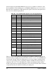
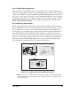
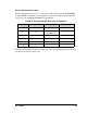
Selected signals from the Rabbit 4000 microprocessor are available on header J2 of the
Prototyping Board. The remaining ports on the Rabbit 4000 microprocessor are used for
RS-232 serial communication. Table B-2 lists the signals on header J2 and explains how
they are used on the Prototyping Board.
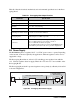
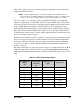
There is a 1.3" × 2" through-hole prototyping space available on the Prototyping Board.
The holes in the prototyping area are spaced at 0.1" (2.5 mm).
+3.3 V, +5 V, and GND traces
run along the top edge of the prototyping area for easy access.
Small to medium circuits
can be prototyped using point-
to-point wiring with 20 to 30 AWG wire between the proto-
typing area, the
+3.3 V, +5 V, and GND traces,
and the surrounding area where surface-
mount components may be installed.
Small holes are provided around the surface-mounted
components that may be installed around the prototyping area.
Table B-2. Use of Rabbit 4000 Signals on the Prototyping Board
Pin Pin Name Prototyping Board Use
1 +3.3 V +3.3 V power supply
2 GND
3 /RST_OUT Reset output from reset generator
4 /IORD External read strobe
5 /IOWR External write strobe
6 /RESET_IN Input to reset generator
8–15 PA0–PA7 Output, pulled high
16 PB0 CLKB (used by A/D converter RCM4000 only)
17 PB1 Programming port CLKA
18 PB2 LED DS2 (normally high/off)
19 PB3 LED DS3 (normally high/off)
20 PB4 Switch S2 (normally open/pulled up)
21 PB5 Switch S3 (normally open/pulled up)
22–23 PB6–PB7 Output, pulled high
24–25 PC0–PC1 Serial Port D (RS-232, header J4) (high)
26–27 PC2–PC3 Serial Port C (RS-232, header J4) (high)
28–29 PC4–PC5 Serial Port B (used by A/D converter RCM4000 only)
30–31 PC6–PC7 Serial Port A (programming port) (high)
32–39 PE0–PE7 Parallel I/O, Output, I0–I7
40–47
LN0–LN7 A/D converter inputs (RCM4000 only)
PD0–PD7 Output, pulled high
48 CONVERT A/D converter CONVERT input (RCM4000 only)
49 VREF A/D converter reference voltage (RCM4000 only)
50 AGND A/D converter ground (RCM4000 only)