
International User's Manual Network Adapter RCM4000


User’s Manual 105
B.5 Prototyping Board Jumper Configurations
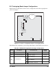
Figure B-8 shows the header locations used to configure the various Prototyping Board
options via jumpers.
Figure B-8. Location of Configurable Jumpers on Prototyping Board
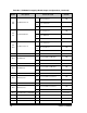
Table B-6 lists the configuration options using either jumpers or 0 Ω surface-mount resistors.
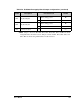
Table B-6. RCM3400 Prototyping Board Jumper Configurations
Header Description Pins Connected
Factory
Default
JP1 +5 V Current Measurement 1–2 Via trace or jumper Connected
JP2 +3.3 V Current Measurement 1–2 Via trace or jumper Connected
JP3
JP4
PC0/TxD/LED DS2
JP3
1–2
TxD on header J4
×
JP4
1–2
PC0 to LED DS2
n.c. PC0 available on header J2
JP1
JP2
JP25
UX49
JP23
JP11
JP15
JP19
JP21
JP22
JP20
JP17
JP13
JP16
JP6
JP5
JP12
JP4
JP3
JP14
JP8
JP7
JP18
JP9
JP10
JP24