
International User's Manual Network Adapter RCM4000


User’s Manual 21
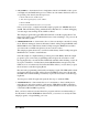
• SIMPLE5WIRE.C—This program demonstrates 5-wire RS-232 serial communication
with flow control on Serial Port D and data flow on Serial Port C.
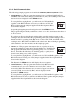
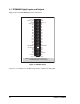
To set up the Prototyping Board, you will need to tie TxD and RxD
together on the RS-232 header at J4, and you will also tie TxC and
RxC together using the jumpers supplied in the Development Kit as
shown in the diagram.
Once you have compiled and run this program, you can test flow con-
trol by disconnecting TxD from RxD while the program is running. Characters will no
longer appear in the STDIO window, and will display again once TxD is connected
back to RxD.
If you have two Prototyping Boards with modules, run this sample program on the
sending board, then disconnect the programming cable and reset the sending board so
that the module is operating in the Run mode. Connect TxC, TxD, and GND on the
sending board to RxC, RxD, and GND on the other board, then, with the programming
cable attached to the other module, run the sample program. Once you have compiled
and run this program, you can test flow control by disconnecting TxD from RxD as
before while the program is running.
• SWITCHCHAR.C—This program demonstrates transmitting and then receiving an
ASCII string on Serial Ports C and D. It also displays the serial data received from both
ports in the STDIO window.
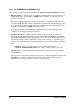
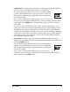
To set up the Prototyping Board, you will need to tie TxD and RxC
together on the RS-232 header at J4, and you will also tie RxD and
TxC together using the jumpers supplied in the Development Kit as
shown in the diagram.
Once you have compiled and run this program, press and release
switches S2 and S3 on the Prototyping Board. The data sent between the serial ports
will be displayed in the STDIO window.
J4
RxC TxC
GND
TxD RxD
J4
RxC TxC
GND
TxD RxD