T r a n s P o r t ®W R 4 4 v 2 Wireless Routers Installation Guide January 9, 2012 90001264_A
TransPort® WR44v2 Installation Guide Disclaimer Digi International makes no representations or warranties with respect to the contents or use of this manual, any software drivers or associated application software provided with this product and specifically disclaims any expressed or implied warranties of merchantability or fitness for any particular purpose.
TransPort® WR44v2 Installation Guide Special notes on safety for wireless routers Digi International products are designed to the highest standards of safety and international standards compliance for the markets in which they are sold. However, cellular-based products contain radio devices which require specific consideration. Please take the time to read and understand the following guidance. Digi International assumes no liability for an end user’s failure to comply with these precautions.
TransPort® WR44v2 Installation Guide Table of Contents 1 Package Contents ......................................................................5 2 Introduction ................................................................................6 2.1 Enclosure Features ...........................................................................................7 2.2 Front Panel Features ........................................................................................8 2.3 Rear Panel Features .............
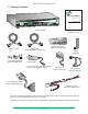
TransPort® WR44v2 Installation Guide 1 Package Contents TransPort WR44 v2 Wireless Routers Installation Guide TransPort WR44 Installation Guide Ethernet Cable Power Supply Adapters [Non-US models only] PSTN Cable [PSTN & DialServ models only] Telemetry Connector [Telemetry models only] Cellular Antenna(s) Power Supply (some models may include a DC Power Cord or have no Power Supply) GPS Antenna [GPS models only] Wi-Fi Antenna [Wi-Fi models only] 15-pin Telemetry Cable [Fleet Card models only] Fle
TransPort® WR44v2 Installation Guide Preface This guide describes the installation procedure for the TransPort WR family of routers. It is intended to provide sufficient information to be able to connect the unit to terminal equipment and power-on the unit. A complete reference guide to the software features that are available on the product is available separately in PDF format and can be downloaded from the Digi International web site (www.digi.com).
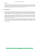
TransPort® WR44v2 Installation Guide 2.1 Enclosure Features TransPort WR44 1 2 2 TransPort WR44 R 3 4 4 TransPort WR44 DSL Variant DSL 1. Commercial Enclosure 2. Mounting Feet 3. Rugged Enclosure 4.
TransPort® WR44v2 Installation Guide 12. Front Panel Features 2.2 10 1 2 3 4 5 6 7 8 9 TransPort WR44 DSL Variant DSL 11 1. USB Host Connector - The USB host connector may be used to connect compatible USB 2.0 client devices such as memory sticks, and serial adapters. The total current available to power USB devices is 0.5A. 2. LED Status Indicator - POWER - Illuminates steady when power is connected. 3.
TransPort® WR44v2 Installation Guide • Constant red - no DSL is detected. • Flashing red - DSL is detected and unit is trying to train up to the DSL signal. • Constant green - DSL is active. • Flashing green - Data is being transferred LED Status Indicator - LINK - Illuminates steady when a wireless data connection has been established.
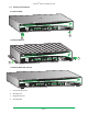
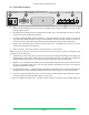
TransPort® WR44v2 Installation Guide 2.3 Rear Panel Features 2 1 WWAN PRIMARY 3 WIFI SECONDARY 4 WWAN SECONDARY WIFI PRIMARY 10 7 9-36VDC 3.5A MAX 8 MAIN AUX. 5 6 LAN3 SERIAL 0 LAN2 LAN1 LAN0 DSL 9 1. Primary Cellular (WWAN) Antenna Connector - This SMA female connector is used to connect the unit’s primary cellular antenna. 2. Secondary Wi-Fi (WLAN) Antenna Connector (Wi-Fi models only) - This SMA male connector is used to connect the unit’s secondary Wi-Fi antenna. 3.
TransPort® WR44v2 Installation Guide 2.4 Under Unit Features TransPort WR44 [Front of Unit] 2 1 3 1 [Rear of Unit] TransPort WR44 R [Front of Unit] 3 [Rear of Unit] 1. Unit mounting holes. 2. SIM slot cover plate mounting hole. 3. Reset button - The reset button allows the user to return the unit to its factory default settings. It is recessed [to avoid accidental reset], and can be accessed via a small 2.5mm hole located on the underside of the unit. 2.4.
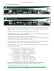
TransPort® WR44v2 Installation Guide 2.5 Additional Hardware Features The TransPort WR44 v2 is available with various hardware options, as shown below: WWAN PRIMARY WWAN SECONDARY WIFI SECONDARY WIFI PRIMARY 9-36VDC 3.5A MAX MAIN AUX.
TransPort® WR44v2 Installation Guide 1. ASY Serial Port (3x) - Provides three additional asynchronous RS232 serial ports using RJ45 connectors. 2. SYN/ASYN Serial Port - Provides an X.21/RS422/RS232 synchronous / asynchronous serial port using a DB25 connector. 3. GPS - Provides GPS capabilities using an SMA male connector. 4. ISDN - Provides an ISDN Basic Rate Interface (BRI) via an RJ45 port. This can be configured either as a TE (terminal endpoint) or as NT-1 (network termination).
TransPort® WR44v2 Installation Guide 3 Installation Mounting Tips The TransPort WR44 should be positioned on a flat, level surface or via a wall-mount, rackmount, or DIN rail mounting brackets (see the Accessories section on page 23 for all options). The unit is designed for indoor use (except for the WR44 R) and should be mounted in a location with adequate ventilation. Also, do not expose the unit to extremes of heat or cold, strong magnetic fields, or liquids.
TransPort® WR44v2 Installation Guide The TransPort WR44 also allows for dual network installations where one wireless service can be used as a back-up in the event that the primary service fails. These installations cannot be used to access two networks simultaneously. By default, SIM 1 is used for access to the primary network and SIM 2 is used for the back-up network.
TransPort® WR44v2 Installation Guide 4 Configuration Once the unit has been installed and powered up, it needs to be configured to communicate with the LAN and WAN. Configuration is performed either using the Command Line Interface (CLI) or the Web Interface. The Web Interface (accessed via a web browser e.g. Firefox, IE, Chrome) is the recommended configuration option for most users.
TransPort® WR44v2 Installation Guide The Quick Start Wizard is located in the Getting Started section on the Home menu. 4.2.1 Cellular: CDMA If your unit is to be used on a CDMA network, the embedded module must be provisioned on the network before it can make a connection.
TransPort® WR44v2 Installation Guide 4.2.1.1 CDMA Provisioning CDMA provisioning is different from GSM since CDMA (in most cases) does not use a SIM card. The CDMA modem provisioning process creates a CDMA data connection to the mobile carrier network. This authenticates the modem and retrieves account information which is written to flash memory on the modem module itself, not the Digi’s configuration file.
TransPort® WR44v2 Installation Guide 4.3 Command Line Interface (CLI) In order to configure the unit serially, ensure that the unit is connected to a PC (as outlined in Step 5 on page 15 of the Installation section). Also, terminal emulation software (such as HyperTerminal) will be required. 4.3.1 CLI Notes • To view the current configuration settings, enter the command CONFIG C SHOW. • To save changes made to the unit, enter the command CONFIG 0 SAVE.
TransPort® WR44v2 Installation Guide To stop the DHCP server from serving addresses, use the following command: Command DHCP 0 IPMIN X Description Removes the minimum IP address that will be server via DHCP, disabling the DHCP server As an example, to stop the DHCP sever from DHCP requests, enter the command DHCP 0 IPMIN !. The ! variable is used to remove a value or set it back to its default.
TransPort® WR44v2 Installation Guide 5 Troubleshooting 5.1 Troubleshooting Resources There are several resources available to you for support of your Digi product or resolving configuration difficulties at Digi’s Support site, http://www.digi.com/support/. Try these troubleshooting steps to eliminate your problem. After working through these steps and your problem is not solved, try the resources listed below. 1. Digi’s Support knowledge base: http://www.digi.com/support/kbase. 2.
TransPort® WR44v2 Installation Guide 6 Specifications Specifications Digi TransPort WR44 / WR44 R General Features: Dimensions (L x W x H) 5.7” x 8.3” x 1.6” (145 mm x 210 mm x 40 mm) DSL Variant 5.7” x 10.3” x 1.6” (145mm x 262mm x 40mm) Weight 1.98 lb (0.9Kg) DSL Variant 2.5lb (1.
TransPort® WR44v2 Installation Guide 7 Accessories AC Power Supplies North America (NA) 76000823 International (Intl.) 76000823 NA - Extended Temp. 76000790 Intl. - Extended Temp.
TransPort® WR44v2 Installation Guide Antennas - Cellular Direct Mount, Quad Band, 2dBi 76002050 Direct Mount, Penta Band, 2dBi 76002052 Direct Mount, Dual Band, 3dBi DC-ANT-DBDP3 Magnet Mount, Penta Band, 2.5dBi 76002051 Magnet Mount, Dual Band, 4.0dBi DC-ANT-DBHG Glass Mount, Quad Band, 1.5dBi 76000844 Glass Mount, Penta Band, 0dBd 76000845 Surface/Marine Mount, Quad Band, 0dBi 2.15dBi 76000864 Surface/Through-hole Mount, Quad Band, 0dBd 76000846 Surface/Through-hole Mount, Quad Band, 3.
TransPort® WR44v2 Installation Guide Declaration of Conformity EC Declaration Of Conformity We, of Manufacturer's Name: Digi International Manufacturer's Address: 11001 Bren Road East Minnetonka, MN 55343 declare under our sole responsibility that the product: Product Name: TransPort WR44v2 Model Numbers: Reference product list below to which this declaration relates are in conformity with the essential requirements and other relevant requirements of the Directive 2004/108/EC (EMC), Directive 200
TransPort® WR44v2 Installation Guide EC Declaration Of Conformity • • • • • Part Number WR44-NNHH-ZYY-XX Where NN can be: 00, 01, C0, C1, C2, C3, C4, C5, C6, C8, E1, G1, U0, U2, U4, U5, U6, U7, U8 Where HH can be: 00, A1, A3, F1, G1, I1, I3, P1, P3, S1, T1, T2 Where Z can be: C, N, F, G, L, M Where YY can be: A1, A2, A3, A5, E1, E2, E3, E5, S1, S2, S3, S5, V1, V2, V3 or any numeric value Where AA can be: SA, SB, SD, SF, SL, SN, SU, SW, RA, RB, XA, XB, XD, XF, XH, XG, XJ, XK Product Disposal Instructions
Copyright © 2011 Digi International Inc. All rights reserved. Digi, Digi International, the Digi logo, a Digi International Company, the Digi web site, Digi Remote Manager, Digi TransPort, Digi TransPort WR, and Digi TransPort WR44 are trademarks or registered trademarks of Digi International, Inc. in the United States and other countries worldwide. All other trademarks are the property of their respective owners.