
Product manual

©2009DigiInternationalInc. 26
3.RFModuleConfiguration
Programming the RF Module
Refer to the Command Mode section [p25] for more information about entering Command Mode,
sending AT commands and exiting Command Mode. For information regarding module program-
ming using API Mode, refer to the API Operation sections [p57].
Programming Examples
Setup
Sample Configuration: Modify RF Module Destination Address
Sample Configuration: Restore RF Module Defaults
The programming examples in this section require the installation of Digi's X-CTU Software and
a serial connection to a PC. (Digi stocks RS-232 and USB boards to facilitate interfacing with a
PC.)
1. Install Digi's X-CTU Software to a PC by double-clicking the "setup_X-CTU.exe" file. (The file
is located on the Digi CD and www.digi.com/xctu.)
2. Mount the RF module to an interface board, then connect the module assembly to a PC.
3. Launch the X-CTU Software and select the 'PC Settings' tab. Verify the baud and parity set-
tings of the Com Port match those of the RF module.
NOTE: Failure to enter AT Command Mode is most commonly due to baud rate mismatch.
Ensure the ‘Baud’ setting on the ‘PC Settings’ tab matches the interface data rate of the RF mod-
ule. By default, the BD parameter = 3 (which corresponds to 9600 bps).
Example: Utilize the X-CTU “Terminal” tab to change the RF module's DL (Destination Address
Low) parameter and save the new address to non-volatile memory.
After establishing a serial connection between the RF module and a PC [refer to the 'Setup' sec-
tion above], select the “Terminal” tab of the X-CTU Software and enter the following command
lines (‘CR’ stands for carriage return):
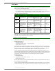
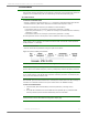
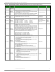
Method 1 (One line per command)
Send AT Command
+++
ATDL <Enter>
ATDL1A0D <Enter>
ATWR <Enter>
ATCN <Enter>
System Response
OK <CR> (Enter into Command Mode)
{current value} <CR> (Read Destination Address Low)
OK <CR> (Modify Destination Address Low)
OK <CR> (Write to non-volatile memory)
OK <CR> (Exit Command Mode)
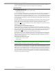
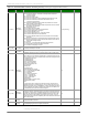
Method 2 (Multiple commands on one line)
Send AT Command
+++
ATDL <Enter>
ATDL1A0D,WR,CN <Enter>
System Response
OK <CR> (Enter into Command Mode)
{current value} <CR> (Read Destination Address Low)
OK<CR> OK<CR> OK<CR>
Example: Utilize the X-CTU “Modem Configuration” tab to restore default parameter values.
After establishing a connection between the module and a PC [refer to the 'Setup' section
above], select the “Modem Configuration” tab of the X-CTU Software.
1. Select the 'Read' button.
2. Select the 'Restore' button.