
Product manual


XBee®/XBee‐PRO®RFModules‐802.15.4‐v1.xEx[2009.09.23]
©2009DigiInternatonal,Inc. 41
D0 - D4 (DIOn Configuration) Commands
<I/O Settings> The D0, D1, D2, D3 and D4 com-
mands are used to select/read the behavior of
their respective AD/DIO lines (pins 20, 19, 18, 17
and 11 respectively).
Options include:
• Analog-to-digital converter
• Digital input
•Digital output
D5 (DIO5 Configuration) Command
<I/O Settings> The D5 command is used to
select/read the behavior of the DIO5 line (pin 15).
Options include:
• Associated Indicator (LED blinks when the
module is associated)
• Analog-to-digital converter
• Digital input
•Digital output
D6 (DIO6 Configuration) Command
<I/O Settings> The D6 command is used to
select/read the behavior of the DIO6 line (pin 16).
Options include:
• RTS flow control
• Analog-to-digital converter
• Digital input
•Digital output
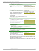
AT Commands:
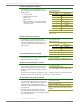
ATD0, ATD1, ATD2, ATD3, ATD4
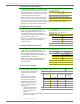
Parameter Range:0 - 5
Parameter Configuration
0 Disabled
1n/a
2ADC
3DI
4DO low
5DO high
Default Parameter Value:0
Minimum Firmware Version Required: 1.x.A0
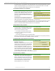
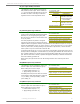
AT Command: ATD5
Parameter Range:0 - 5
Parameter Configuration
0 Disabled
1 Associated Indicator
2ADC
3DI
4DO low
5DO high
Default Parameter Value:1
Parameters 2-5 supported as of firmware
version 1.xA0
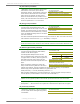
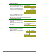
AT Command: ATD6
Parameter Range:0 - 5
Parameter Configuration
0 Disabled
1RTS Flow Control
2n/a
3DI
4DO low
5DO high
Default Parameter Value:0
Parameters 3-5 supported as of firmware
version 1.xA0