XBee™ Adapters, Routers, and Sensors User’s Guide XBee ZNet 2.5 (Series 2) Adapters: XBee RS-232 Adapter XBee RS-232 PH (Power Harvester) Adapter XBee RS-485 Adapter XBee Analog I/O Adapter XBee Digital I/O Adapter XBee Sensor Adapter XBee USB Adapter XStick ZNet 2.5 XBee Wall Router XBee Sensors www.digi.
©2008 Digi International Inc. All Rights Reserved. Digi, Digi International, the Digi logo, ConnectPort, Watchport, and XBee are trademarks or registered trademarks of Digi International, Inc. in the United States and other countries worldwide. All other trademarks are the property of their respective owners. Information in this document is subject to change without notice and does not represent a commitment on the part of Digi International.
Contents Chapter 1 General information .............................................................4 About this guide............................................................................................... 4 Scope ........................................................................................................ 4 Compatibility Note ..................................................................................... 4 Mounting orientation .....................................................
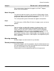
General information General information Chapter 1 This section includes information that applies to all XBee™ Adapter, Router, and Sensor products. About this guide This guide describes the features and functions of XBee Adapter, Router, and Sensor products, including connection and setup information, pinouts, configuration, data retrieval, and LEDs and buttons. This section provides general information that applies to all products. Scope This guide covers all XBee ZNet 2.
General information Additional reference material For additional information about the features and functions of XBee RF modules in XBee Adapters, see these documents. XBee Adapters data sheet http://www.digi.com/pdf/ds_xbeeadapters.pdf XBee Wall Router data sheet http://www.digi.com/pdf/ds_xbeewallrouter.pdf These data sheets provide overviews of XBee Adapter and Wall Router products, features and benefits, and specifications. XBee ZNet 2.5 (Series 2) RF Module Product Manual http://ftp1.digi.
General information Questions and technical support For technical assistance with your product, contact Digi Technical Support at: 801-765-9885 or 877-912-3444 or make an online support request at: http://www.digi.com/support/index.
XBee RS-232 Adapter XBee RS-232 Adapter Chapter 2 Overview The XBee RS-232 Adapter provides short range wireless connectivity to any RS-232 serial device, with available solutions for both mesh (including ZigBee) and point-to-multipoint networks. Unlike an embedded wireless module, which requires design integration and development time, these off-the-shelf adapters provides instant wireless connectivity to existing RS-232 serial devices.
XBee RS-232 Adapter Pinouts The RS-232 connector is an industry-standard DB9 male connector with a DTE configuration, similar to a PC serial port. Pinouts for the connector are: Pin Function Data direction 1 CD Input 2 RXD Input 3 TXD Output 4 DTR Output 5 GND 6 DSR Input 7 RTS Output 8 CTS Input 9 +12VDC switched power out Output Data retrieval Retrieving data from XBee adapters is done by issuing a remote AT IS (Force Sample) command through the XBee API.
XBee RS-232 Adapter Power LED: Assc LED: Indicates that power is on. Illuminated only when adapter is connected to external power only, not when powered by batteries. Not available in lithium-battery models. Indicates the adapter’s ZigBee network association status: LED status Reset button: Ident button: Button press Single Network association On, solid green Not associated On, blinking green Successfully joined Recessed button on underside of the adapter. Performs equivalent of a power-cycle.
XBee RS-232 PH Adapter XBee RS-232 PH Adapter Overview The XBee RS-232 PH Adapter provides short range wireless connectivity to any RS-232 serial device, with available solutions for both mesh (including ZigBee) and point-to-multipoint networks. Unlike an embedded wireless module, which requires design integration and development time, these off-the-shelf adapters provides instant wireless connectivity to existing RS-232 serial devices.
XBee RS-232 PH Adapter Pinouts The RS232 connector is an industry-standard DB9 male connector with a DTE configuration, similar to a PC serial port. Pinouts for the connector are: Pin Function Data direction 1 CD Input Also used for parasitic power input from host. 2 RXD Input Also used for parasitic power input from host. 3 TXD Output 4 DTR Output 5 GND 6 DSR Input Also used for parasitic power input from host.
XBee RS-232 PH Adapter Configuration There are four key attributes of the Serial PH adapter’s firmware that allow it to have a net charge on its batteries: • Sleep Mode (SM) • Idle Time (ST) • Sleep Period (SP) • Sleep Number (SN) Sleep mode, determines what sleeping behavior the adapter has. By default the adapter has cyclical sleep enabled.
XBee RS-232 PH Adapter LEDs and buttons Assoc Assoc LED: Ident Indicates the adapter’s ZigBee network association status: LED status Reset button: Ident button: Button press Single Reset Network association On, solid green Not associated On, blinking green Successfully joined Performs equivalent of a power-cycle. Use a small non-conducive tool with a blunt end to press gently and hold down button. Performs multiple functions for commissioning the adapter in a ZigBee network.
XBee RS-485 Adapter XBee RS-485 Adapter Chapter 4 Overview The XBee RS-485 PH Adapter provides short range wireless connectivity to any RS-485 serial device, with available solutions for both mesh (including ZigBee) and point-to-multipoint networks. Unlike an embedded wireless module, which requires design integration and development time, these off-the-shelf adapters provides instant wireless connectivity to existing RS-485 serial devices.
XBee RS-485 Adapter Pinouts The connector for the adapter is a 6-position wire terminal block. The figure shows Pin 1 of the connector when the adapter is oriented with the mounting tabs, facing upwards (the underside of the adapter). The adapter is switch-selectable between RS-422 half duplex, RS-422 full duplex, and RS-485 modes (see DIP switches, below). The function for several pins varies between RS-422 and RS-485 modes.
XBee RS-485 Adapter DIP switches The XBee RS-485 Adapter has several DIP switches on the underside of the unit, with these settings: DIP Switch Switch settings 1 Not used. It is covered up by the case and not accessible. 2, 3, 4 ON = RS485 OFF = RS422 5, 6 ON = RS485 Bias and line termination on. OFF = RS485 Bias and line termination off. Note: Bias and line termination feature can be used only when powering from the external power supply.
XBee RS-485 Adapter Power LED: Assc LED: Indicates that power is on. Illuminated only when adapter is connected to external power only, not when powered by batteries. Not available in lithium-battery models. Indicates the adapter’s ZigBee network association status: LED status Reset button: Ident button: Button press Single Network association On, solid green Not associated On, blinking green Successfully joined Recessed button on underside of the adapter. Performs equivalent of a power-cycle.
XBee Analog I/O Adapter Chapter 5 XBee Analog I/O Adapter Overview The XBee Analog I/O Adapter provides short range wireless connectivity to any analog device, with available solutions for both mesh (including ZigBee) and point-to-multipoint networks. Unlike an embedded wireless module, which requires design integration and development time, these off-the-shelf adapters provides instant wireless connectivity to existing analog devices.
XBee Analog I/O Adapter Power options Depending on adapter model, there are several powering options. Alkaline battery model This product can be powered by a 9-30VDC external power supply (see "Power requirements" on page 68) or by batteries. Use 3x1.5V “N” alkaline battery cells. To install batteries, insert a screwdriver in the slots in the side of the adapter case and twist to snap off the cover. Insert the batteries following the polarity diagram on the board.
XBee Analog I/O Adapter Pinouts Using the orientation in the previous figure, from right to left, the pinouts are: Analog Mode Pin Ten Volt Current Loop Differential 1 0-10 Volt 4-20 mA Terminal Pair 1 positive 2 0-10 Volt 4-20 mA Terminal Pair 1 negative 3 0-10 Volt 4-20 mA Terminal Pair 2 positive 4 0-10 Volt 4-20 mA Terminal Pair 2 negative 5 Ground Ground Ground +12VDC 50mA max switched power out +12VDC 50mA max switched power out +12VDC 50mA max switched power out DIP switche
XBee Analog I/O Adapter Configuring inputs and outputs Input selection Six control lines from the XBee module are used to place the four external terminals into the desired input mode. The power-on default is 0-10VDC on all four terminals. Set the analog mode The AT commands D8, D4, and D6 set the analog mode for terminals 1 and 2. P0, D7, and P2 set the mode for terminals 3 and 4. All other configurations are invalid. A Python module named xbeeain.
XBee Analog I/O Adapter Enable a terminal line for measurement To enable a terminal line for measurement, the following analog I/O lines have to be set to value 2: • D0 • D1 • D2 • D3 D0, D1, D2, and D3 represent terminal lines 1, 2, 3, and 4 respectively. In the case of a terminal pair in differential mode, only the first terminal of the terminal pair should be enabled. To disable a terminal line, set the respective analog I/O line to value 0.
XBee Analog I/O Adapter Power output specifications External terminal 6 is a power-out pin. It can be set to either battery pack voltage out or +12VDC at 50mA out via DIP switches 1 and 2. External terminal 5 is a system ground pin. This ground pin should be used for all external ground connections for both power and input connections. DIP switch 1 enables battery pack voltage minus .5VDC to terminal 6, resulting in 4VDC out with new alkaline batteries, or 3.1VDC with new lithium battery.
XBee Analog I/O Adapter Python modules for configuring inputs and outputs Digi provides a library of Python modules for configuring inputs and outputs on the adapter and retrieving data from the adapter. These modules are available for downloading from www.digi.com/din/docs, in a file named XBee Adapter Libraries. By uploading these Python modules to the gateway that serves as a coordinator for the adapter, you can use them in your own programs.
XBee Analog I/O Adapter Use xbeeain.py functions in Python programs To use the functions in the module xbeeain.py, any Python programs must contain the next statement: from xbeeain import * The functions and arguments in module xbeeain.py are as follows.
XBee Analog I/O Adapter Data retrieval To retrieve measurement data from the XBee Analog I/O Adapter, use these Python modules, provided in the XBee Adapter Libraries: • xbeeain.py: Issues the AT IS command to retrieve the data. • sensor_io.py: Decodes the output of the AT IS command. Byte structure returned by IS command The AT IS (Force Sample) command is used to force a read of all enabled analog I/O lines.
XBee Analog I/O Adapter Bitmask for digital sampling In this bitmask, bit 0 is the lease significant bit. The measurement associated with AD0 is from terminal line 1, AD1 is from terminal line 2, etc.
XBee Analog I/O Adapter Digital sample This field should be ignored. Analog sample Contains the measured results from the analog-enabled digital I/O lines. This example is for a 10-bit sample. Each measurement is 2 bytes long, and ranges between 0-1023 for value (10 bit resolution). The lowest lines are always first, so if digital I/O 0 and 2 were enabled, the first 2 bytes would represent digital I/O 0’s measurement and the second two bytes would represent digital I/O 2’s measurement.
XBee Analog I/O Adapter Power LED: Assc LED: Indicates that power is on. Illuminated only when adapter is connected to external power only, not when powered by batteries. Not available in lithium-battery models. Indicates the adapter’s ZigBee network association status: LED status Reset button: Ident button: Button press Single Network association On, solid green Not associated On, blinking green Successfully joined Recessed button on underside of the adapter. Performs equivalent of a power-cycle.
XBee Digital I/O Adapter XBee Digital I/O Adapter Chapter 6 Overview The XBee Digital I/O Adapter provides short range wireless connectivity to any digital device, as well as an interface to logic-level inputs and sinking driver output. Solutions are available for both mesh (including ZigBee) and point-to-multipoint networks.
XBee Digital I/O Adapter Connection and power-on 1. Connect the wires for the desired digital device to the connector for the adapter. The connector for the adapter is a 6-position wire terminal block. The connector accommodates wire gauges from 16AWG to 30AWG. The figure shows Pin 1 of the connector when the adapter is oriented with the mounting tabs, facing upwards (the underside of the adapter).
XBee Digital I/O Adapter DIP switches The XBee Digital I/O Adapter has several DIP switches on the underside of the unit, with these settings: DIP Switch Switch settings 1 Enables and disables direct battery pack voltage output. On=battery power out Off=no battery power out 2 Enables and disables +12V power out. On=+12V power out Off=no +12V power out 3 Turns on 10K pullup on terminal 1 to 3VDC. 4 Turns on 10K pullup on terminal 2 to 3VDC.
XBee Digital I/O Adapter Configuring inputs and outputs As shown in the pinouts table, the XBee Digital I/O Adapter product has four external terminals that can be set as either a digital input or a sinking driver output. The XBee module controls the sinking drivers on pins 11, 16, 12, 4 for terminals 1, 2, 3, 4 respectively. The AT commands to the XBee module for the output function are D4, D6, D7, P2 for terminals 1, 2, 3, 4 respectively.
XBee Digital I/O Adapter Power output specifications External terminal 6 is a power-out pin. It can be set to either battery pack voltage out or +12VDC at 50mA out via DIP switches 1 and 2. External terminal 5 is a system ground pin. This ground pin should be used for all external ground connections for both power and input connections. DIP switch 1 enables battery pack voltage minus .5VDC to terminal 6, resulting in 4VDC out with new alkaline batteries, or 3.1VDC with new lithium battery.
XBee Digital I/O Adapter Python modules for configuring inputs and outputs Digi provides a library of Python modules for configuring inputs and outputs on the adapter and retrieving data from the adapter. These modules are available for downloading from www.digi.com/din/docs, in a file named XBee Adapter Libraries. By uploading these Python modules to the gateway that serves as a coordinator for the adapter, you can use them in your own programs.
XBee Digital I/O Adapter Use xbeedin.py functions in Python programs To use the functions in the module xbeedin.py for programming inputs and outputs, any Python programs you create must contain this statement: from xbeedin import * The functions and arguments in module xbeedin.py are as follows.
XBee Digital I/O Adapter Data retrieval To retrieve measurement data from the XBee Digital I/O Adapter, use these Python modules, provided in the XBee Adapter Libraries: • xbeedin.py: Issues the AT IS command to retrieve the data. • sensor_io.py: Decodes the output of the AT IS command. To enable a terminal line for measurement, the following digital I/O lines have to be set to value 3: • D8 • D1 • D2 • D3 D8, D1, D2, and D3 represent terminal lines 1, 2, 3, and 4 respectively.
XBee Digital I/O Adapter Bit mask for digital sampling In this bitmask, bit 0 is the lease significant bit. The measurement associated with AD0 is from terminal line 1, AD1 is from terminal line 2, etc.
XBee Digital I/O Adapter LEDs and buttons blinking green Assc Power LED: Assc LED: solid green Ident Reset button Power Indicates that power is on. Illuminated only when adapter is connected to external power only, not when powered by batteries. Not available in lithium-battery models.
XBee Digital I/O Adapter Reset button: Ident button: Button press Single Recessed button on underside of the adapter. Performs equivalent of a power-cycle. Use a small non-conducive tool with a blunt end to press gently and hold down button. Recessed button on power end of the adapter between Assc and Power LEDs. Performs multiple functions for commissioning the adapter in a ZigBee network. Consecutive button presses must occur within 800 ms of each other to perform the desired action.
XBee Sensor Adapter XBee Sensor Adapter Chapter 7 Overview The XBee Sensor Adapter provides short range wireless connectivity to Digi Watchport® Sensors, with available solutions for both mesh (including ZigBee) and point-to-multipoint networks. Unlike an embedded wireless module, which requires design integration and development time, these off-the-shelf adapters provides instant wireless connectivity to existing Watchport Sensors.
XBee Sensor Adapter Pinouts The XBee Sensor Adapter uses an industry-standard RJ45 10 pin modular jack with these pinouts: Pin Function 1 Not used. 2 Not used. 3 Not used. 4 GND 5 1-wire (sensor) data 6 +5VDC switched power out. 7 GND 8 +5VDC switched power out. 9 General-purpose logic input for moisture sensor. 10 Not used.
XBee Sensor Adapter Sensor function configuration and data retrieval Digi provides a Python module for configuring sensor functions and retrieving data from XBee Sensor Adapters. This module is named xbee_sensor.py and is available for downloading from www.digi.com/din/docs, in a file named XBee Adapter Libraries. By uploading this Python module to the gateway that serves as a coordinator for the adapter, you can use it in your own programs.
XBee Sensor Adapter LEDs and buttons blinking green Assc Power LED: Assc LED: solid green Ident Power Indicates that power is on. Illuminated only when adapter is connected to external power only, not when powered by batteries. Not available in lithium-battery models.
XBee Sensor Adapter Button press Single Network association Action Associated • • If adapter is asleep, wakes unit for 30 seconds. Sends a Node Identification broadcast transmission. All devices that receive this transmission will blink their Associate LED rapidly for 1 second. All API devices that receive this transmission will send a Node Identification frame out their UART (universal asynchronous receiver/transmitter) (API ID 0x95).
XBee USB Adapter XBee USB Adapter Chapter 8 Overview The XBee USB Adapter provides short range wireless connectivity to any USB device, with available solutions for both mesh (including ZigBee) and point-to-multipoint networks. Unlike an embedded wireless module, which requires design integration and development time, these off-the-shelf adapters provides instant wireless connectivity to existing USB devices.
XBee USB Adapter LEDs and buttons There is one LED and one button on the end of the adapter opposite the USB connector: Assoc Reset Associate/Power LED; blinking green=associated Associate/ Power LED: Indicates power and the adapter’s ZigBee network association status: LED status Reset button: Reset button Network association On, solid green Powered and not associated. On, blinking green Powered and associated. Performs a reset.
XStick ZNet 2.5 XStick ZNet 2.5 Chapter 9 Overview The XStick ZNet 2.5 is a USB peripheral module adapter that provides short-range wireless connectivity to a ZigBee Mesh network. Power requirements The XStick ZNet 2.5 is a USB bus-powered device. Connection and startup Plug the XStick ZNet 2.5 into the USB connector of a PC, or use a USB extension cable. The extension cable must be no more than 3 meters long. Download and install device driver The XStick ZNet 2.5 requires a device driver, FT232R.
XBee Wall Router Chapter 10 XBee Wall Router Overview ZigBee technology enables low-cost, low-power networking of sensors, controllers and other such devices in self-configuring, self-healing wireless mesh networks. Digi's XBee Wall Router is a small extender used to create the backbone of a ZigBee network or to expand the range of a ZigBee network so that other ZigBee devices can seamlessly communicate with one another.
XBee Wall Router Connection and startup 1. Plug the XBee Wall Router into an outlet. 2. To make sure your XBee Wall Router is properly connected to the ZigBee network, check the Associate/Power LED, as described above. 3. Discover the XBee Wall Router in the ZigBee network and change configuration settings as needed, as described in "Configuration with a ConnectPort X gateway" on page 61.
XBee Wall Router Upload Python modules to gateway 1. Go to www.digi.com/din/docs. 2. In the list of downloadable files, select and download file XBee Adapter Libraries. 3. Unzip the downloaded file. 4. Read the readme file. 5. Open the web interface for the gateway, go to Applications > Python. 6. In the Upload File edit box, enter the file name for the XBee Adapter Libraries, DigiXBeeDrivers.zip, using the Browse button as needed, and click Upload.
XBee Wall Router Data retrieval To retrieve measurement data from the XBee Wall Router, use these Python modules, provided in the XBee Adapter Libraries: • xbeewr.py: Issues the AT IS command to retrieve the data from the integrated sensors. • sensor_io.py: Decodes the output of the AT IS command.
XBee Wall Router Associate/ Power LED: Indicates power and the Wall Router’s ZigBee network association status: LED status Reset/ Ident button: Button press Single Network association On, solid green Not associated On, blinking green Successfully joined Performs a reset and multiple functions for commissioning the Wall Router in a ZigBee network. Use a small non-conducive tool with a blunt end to press gently and hold down button.
XBee Sensors Chapter 11 XBee Sensors Overview The XBee Sensor family is a group of Zigbee-enabled, battery-powered sensors incorporating an XBee module. Part of Digi's Drop-in Networking solutions, XBee Sensors read real-time data from sensors such as temperature, humidity, and light. This data can be retrieved and transmitted through wireless communications in a ZigBee infrastructure.
XBee Sensors Connection and power-on Insert batteries. Device power is indicated by the green ASSC LED on the front panel of the XBee Sensor. Discover the XBee Sensor in the ZigBee network and change configuration settings as needed, as described in "Configuration with a ConnectPort X gateway" on page 61.
XBee Sensors Upload Python modules to gateway 1. Go to www.digi.com/din/docs. 2. In the list of downloadable files, select and download file XBee Adapter Libraries. 3. Unzip the downloaded file. 4. Read the readme file. 5. Open the web interface for the gateway, go to Applications > Python. 6. In the Upload File edit box, enter the file name for the XBee Adapter Libraries, DigiXBeeDrivers.zip, using the Browse button as needed, and click Upload.
XBee Sensors Use xbeelth.py functions in Python programs To use the functions in the module xbeelth.py for programming light, temperature, and humidity functions in a XBee Sensor /L/T/H product, any Python programs you create must contain this statement: from xbeelth import * The functions and arguments in module xbeelth.
XBee Sensors Additional programming resources For further information on writing Python programs and using Python functions, see: • Digi Python Programming Guide http://ftp1.digi.com/support/documentation/90000833_b.pdf • The Python Support Forum on digi.com http://www.digi.com/support/forum/forum.jspa?forumID=104 For more information about AT commands, see: • XBee ZNet 2.5 (Series 2) RF Module data sheet http://www.digi.com/pdf/ds_xbeemodules.pdf • XBee ZNet 2.
XBee Sensors LEDs, buttons, and integrated sensors XBee Sensors have one button and one LED. XBee Sensor /L/T models have integrated light and temperature sensors. XBee Sensor /L/T/H models have integrated light, temperature, and humidity sensors.
XBee Sensors Associate/ Power LED: Indicates power and the XBee Sensor’s ZigBee network association status: LED status Reset/ Ident button: Network association On, solid green Not associated On, blinking green Successfully joined Performs a reset and multiple functions for commissioning the XBee Sensor in a ZigBee network. Use a small non-conducive tool with a blunt end to press gently and hold down button.
Configure XBee radio settings Chapter 12 Configure XBee radio settings There are several configurable radio settings in XBee Adapter, Router, and Sensor products, including the PAN ID, the node identifier or name for the unit, and timeout and scanning settings. This chapter shows how to configure your XBee product through the gateway’s web interface.
Configure XBee radio settings Discover the device and view the network 1. In the gateway’s web interface, select Administration > System Information from the menu. The System Information page is displayed.
Configure XBee radio settings 2. From the list of System Information links, click Mesh Network. The Mesh Network page is displayed. It shows several settings for the gateway, followed by the Network View of the Mesh Devices. In the Type column, the ZigBee module in the gateway is listed as the coordinator, and any XBee adapter/router/sensor products discovered are listed as routers. View and change XBee radio settings as needed 1. Select Configuration > Mesh Network from the menu.
Configure XBee radio settings 2. In the list under Network View of the Mesh Devices, locate your product by its physical address. This address is printed on a label on the bottom of the unit. Click on the Network Address or Physical Address to open the product’s settings page. 3. The Mesh Network Configuration page is displayed. View and change configuration settings as needed. To apply configuration changes, click Apply.
Configure XBee radio settings Basic radio settings control basic operation of the XBee Module in a ZigBee network. • PAN ID: Sets the PAN (Personal Area Network) ID, in hexadecimal. This is the preferred PAN ID for the ZigBee network. All Digi Drop-in Networking products have a default PAN ID of 0x234. A PAN ID of FFFF causes the XBee Module to select a random PAN ID. Otherwise, the specified ID will be used.
Configure XBee radio settings Advanced radio settings control behavior of the XBee Module at a more detailed level. Generally, these settings can be left at their defaults. • Transmit Power Level: Sets the power level at which the XBee Module transmits conducted power.
Hardware specifications Hardware specifications Chapter 13 XBee Adapters Hardware specifications for XBee Adapters (Sheet 1 of 3) Specification Environmental Operating temperature Value XBee RS-232 Adapter, XBee RS-485 Adapter, XBee Analog I/O Adapter, XBee Digital I/O Adapter, XBee Sensor Adapter, XBee USB Adapter: -40° C to 70° C (-40° to 158° F) Operating temperature for powering options: The temperature range of the UL/C-UL Listed power supply must be 40C to +70C minimum to meet the allowed ambien
Hardware specifications Hardware specifications for XBee Adapters (Sheet 2 of 3) (Continued) Specification Power requirements Value DC power input XBee RS-232 Adapter, XBee RS-485 Adapter, XBee Analog I/O Adapter, XBee Digital I/O Adapter, XBee Sensor Adapter: External power supply varies by model: • Alkaline battery model: UL /c-UL Listed ITE or Class II external power supply, with output rated between 9 to 30VDC, with a current rating of 300mA or greater; locking-barrel connector of 2.1mm x 5.
Hardware specifications Hardware specifications for XBee Adapters (Sheet 3 of 3) (Continued) Specification Dimensions Value XBee RS-232 Adapter, XBee RS-485 Adapter, XBee Analog I/O Adapter, XBee Digital I/O Adapter, XBee Sensor Adapter: Width 4.26 cm (1.68 in) Height 2.53 cm (0.99 in) Length 9.84 cm (3.87 in) Weight 65.0 g (2.29 oz) XBee RS-232 PH Adapter, XBee USB Adapter: Width 4.57 cm 1.80 in) Height 2.10 cm (0.83 in) Length 7.29 cm (2.87 in) Weight 45.36 g (1.
Hardware specifications XStick ZNet 2.5 Specification Value Environmental Operating Temperature -40ºC to 85ºC (-40° to 185° F) Power Requirements Supply Voltage 5V from USB port of PC Operating Current (Transmit) 51mA Operating Current (Receive) 47mA Power-down Current Do not put the XStick in sleep mode. Width 1.78 cm (0.7 in) Height 1.02 cm (0.4 in) Length 4.57 cm (1.8 in) Weight 7.5 g (0.265 oz) Operating Frequency Band 2.
Hardware specifications XBee Wall Router Specification Environmental Value Operating temperature -20° C to 75° C (-4° F to 167° F) Relative humidity 5% to 95% (non-condensing) Power requirements AC power input Universal AC input (85VAC to 265VAC) Dimensions Width 5.0 cm (2.87 in) Height 3.50 cm (1.37 in) Length 7.30 cm (2.87 in) Weight 70.87 g (2.
Hardware specifications XBee Sensors Specification Environmental Value Operating temperature -18° C to +55° C (-64.4° F to 131° F) Relative humidity 5% to 95% (non-condensing) Power requirements AC power input Alkaline Batteries 3 x 1.5V Alkaline battery cells Dimensions Width 6.35 cm (2.50 in) Height Height: 3.30 cm (1.30 in) Length 6.85 cm (2.70 in) Weight 0.35 lb (0.158 kg) with batteries installed, 0.20 lb (0.
Safety statements Safety statements Chapter 14 Class I Division 2, Groups A, B, C, D Hazardous location XBee Adapter, Sensor, and Router products are intended for use in ordinary locations only. The device and any leads for the device may not be extended into a Hazardous Location. This device has not been evaluated for use in wet locations or near combustible liquids, fumes, or vapors.