
User`s guide

XBee Analog I/O Adapter
23
Power output specifications
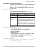
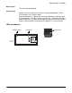
External terminal 6 is a power-out pin. It can be set to either battery pack
voltage out or +12VDC at 50mA out via DIP switches 1 and 2.
External terminal 5 is a system ground pin. This ground pin should be used
for all external ground connections for both power and input connections.
DIP switch 1 enables battery pack voltage minus .5VDC to terminal 6,
resulting in 4VDC out with new alkaline batteries, or 3.1VDC with new
lithium battery. DIP switch 2 enables +12VDC to terminal 6. Only one
switch should be on at a time. No damage will happen if both are set to on,
but the output will default to the +12VDC output and increased parasitic
battery drain will result.
The battery pack voltage is on terminal 6 all the time, and is not gated with
the sleep of the module when DIP switch 2 is on. Any current draw from
terminal 6 will result in reduced battery life.
When DIP switch 2 is on, the +12VDC at 50mA max is provided at terminal
6. This power is gated by both the sleep of the module and AT command
P3. For this power setting to be on, the XBee module needs to be awake
and AT command P3 set to a high level.