
User Manual
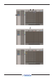

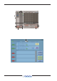
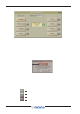


Table Of Contents
- Contents (Appendix A)
- A1.1 Optocore V221 - Introduction .......
- A1.1.1 System Overview .......
- A1.1.2 Opto V220 (DiGiRacks) and Opto V221 (SD Racks) .......
- A1.1.3 Replacing DiGiRacks with SD Racks .......
- A1.1.4 Replacing SD Racks with DiGiRacks .......
- A2.1 The Audio IO Panel .......
- A2.1.1 Layout .......
- A2.1.2 Quick Start Guide for SD V370+ and Optocore V221 .......
- A2.1.3 Audio Sync .......
- A2.1.4 The Port List .......
- A2.1.5 Managing Ports .......
- A2.1.6 SD Rack Splits .......
- A3.1 SD Series Dual Loop Optocore Systems .......
- A3.1.1 Important Considerations .......
- A3.2.1 Setting up a Dual Loop System .......
- A3.2.2 Console Snd/Rcv Ports .......
- A3.2.3 Single Loop Console on Loop 2 .......

DiGiCo Optocore V221
A1-13
The simplest way to create the Console Opto Receive Ports is to press the Conform All Ports button on all the other consoles and
this will automatically create the relevant Receive Ports,
IMPORTANT: When these Ports are added an Optocore Remap is required and this will only work correctly if all the
consoles in the system have matching Send and Receive Ports.
A2.1.6 SD Rack Splits ....................................................................
The SD Rack offers 2 dedicated Split outputs - Main and Aux plus the ability to split any input card to any output card.
If the rack is running at 48KHz, each rack split output provides a 48Khz Split.
If the rack is running at 96KHz the Main split output provides 96Khz channels 1-28 and the Aux split output provides 96KHz
channels 29-56.
Alternatively, If the rack is running at 96KHz each split output can provide 56 channels at 48KHz.
The setting of these modes can only be adjusted on the SD Rack itself - please see the SD Rack documentation for details.
Each split can have automatic Gain Tracking that will compensate the output level for any changes in the relevant input gain.
All of these functions can be controlled on the rack itself through its own menu system but the console Audio I/O panel can also be used.
Be very careful when adjusting these parameters because they will obviously have a potentially dramatic effect on the rack’s functionality.
NOTE: A card split cannot be activated if the relevant output card has already been allocated to Optocore - it must be released
by the console that it using it first.
S p lit Sele ct ed
In p ut Card
Activ at e GT for
sel ec t e d ca r d
Reset GT for
se lect ed card
Reset GT for Main/Au
x
Split Outputs
SD Rack MAD I Split Contr ol
Gain tracking On/Off and Reset
A3.1 SD Series Dual Loop Optocore Systems
A3.1.1 Important Considerations ..................................................
The SD Series Optocore implementation is designed to allow 2 independent fibre loops to exist, with up to 14 SD Racks and 504
Channels of audio per loop at both 48K and 96K. This results in any dual loop console having access to 1008 Channels of IO,
from up to 28 IO locations across the 2 loops.
Both the SD7 and SD5 have the ability to have 2 Optocore loops fitted.
When using a dual loop system, the following stipulations apply:-
NOTE: Dual loop consoles must have the lowest ID’s in the system
In a system consisting of a dual loop SD7 and two Single loop SD10s, the SD7 Optocore Network ID must be 1+2. The SD10s can
be set to any other primary ID eg 3, 5, 7 or 9.
In a system with two dual loop SD7s and two single loop SD10s, the 2 SD7s would have to have Optocore Network IDs of 1+2 &
3+4 and the SD10s would have IDs of either 5, 7 or 9.
NOTE: Loop 1 and Loop 2 must be independent
Loop 1 and Loop 2 fibres cannot be mixed. Anything connected to loop 1 can only exist on loop 1 and anything connected to loop
2 can only be connected to loop 2.
NOTE: There can only be one Loop 2
In a multi console, dual loop system, anything connected to loop 2 on one console must be present on loop 2 of all other consoles
in the system. Each console cannot have its own independent loop 2 connection.
Engine input and output limits
The Optocore system can create a map for 1008 channels of audio across the two loops, however each engine can only have
access to 496 inputs and 496 outputs across the 2 loops. Which inputs/outputs each console has access to is set in the Audio IO
page.