
User Manual

DiGiCo SD Series Broadcast Options
1-11
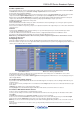
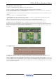
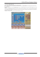
To Edit a Speaker Set
Select a Speaker Set in the column on the left hand side or define a new one by pressing one of the buttons in the column marked New.
The Delete button will prompt you to Select All or a Range of Speaker Sets to remove from the list.
A new monitor can be named in the name box.
Each signal of the Speaker Set can be sent to a specific speaker by pressing one of the Select Signal buttons and choosing a speaker
output socket from the Speaker Output Route panel - to open this panel press the Output button next to the Trim control.
When the first (eg Left) Speaker Output Route is selected the other signals (right etc) will be automatically routed to the subsequent
output sockets. This function can be manually overridden by routing signals individually to outputs of your choice.
The Trim control adjusts the output level to each speaker.
Insert Send and Receive
The Insert Send and Receive buttons allow you to define send and return sockets for patching processors into your speaker system. It
works in the same way as the channel insert settings.
Select a send socket which corresponds to your processor's input and a return from the output of the processor. This can be an internal or
external processor.
Calibration
The buttons in the Calibration section of the panel allow you to set your monitoring levels to preset values and when pressed, the
console's Speaker level rotary pot is bypassed.
To define the calibrate levels, use the name box and level controls, set appropriate labels and levels for Calibration 1 and 2.
Pressing one of the wide grey buttons beneath the level controls switches Calibration mode on.
NOTE: be very careful with this feature as when it is active you will no longer have speaker level control from the console’s
worksurface speaker level pot.
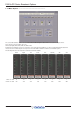
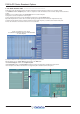
Configuring Sources
The 2 rows of buttons marked 1 to 8 are assigned to the Monitoring Source buttons in the Master Section of the console worksurface.
Each of these buttons can represent a set of signals which will be a potential feed to the speakers. They will typically include different sets
of Mono, Stereo, LCRS or 5.1 busses or inputs.
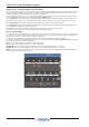
Define Matrix Sources Matrix Source Routing & Upmix/Downmix
In the illustration above there are 4 different sources assigned to buttons 1 to 4 and any source or combination of sources can be
monitored by pressing the relevant worksurface buttons.
If required, you could also set up a Source Switch Toggle which would toggle between different sets of sources by simply pressing one
of the 3 Toggle Switches.
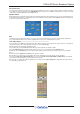
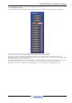
To Assign Control Room Sources
If you touch one of the Source Select white label boxes in the Monitoring panel, a new panel (see above) will appear which allows you to
assign the sources.
Touch one of the sources by touching it on the screen and then touch the Assign button. Now select one of the button numbers to assign
it to the button.
In Manual mode, multiple sources can be monitored at one time.
Selecting Single mode on the main Monitoring panel will switch off the current sources when a new one is selected.
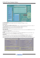
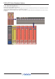
To Create or Edit Control Room Sources
Touch one of the source button labels to open the Edit Sources panel.
You may select an existing source in the column on the left hand side or define a new one by pressing one of the buttons in the column
marked New.
The Delete button will prompt you to Select All or a Range of sources to remove from the list.
A new source can be named in the Name box and then each signal of the source can be defined by pressing one of the Select Signal
buttons, then pressing the Input button and choosing a source from the list of signal groups and signals.
NOTE: If you select a source for the left signal at the top of the list the following signals will, by default, be set to consecutive sockets in
that group.
These selections do not have to be consecutive sockets, you may manually override the default selection and choose sources from
different groups.