SD10 Operation Manual User Manual - Getting Started To be read in conjunction with the SD Series Software Reference User Manual Version B for Software Versions 4.0.
SD10 Operation Manual Copyright © 2014 Digico UK Ltd All rights reserved. No part of this publication may be reproduced, transmitted, transcribed, stored in a retrieval system, or translated into any language in any form by any means without the written permission of Digico UK Ltd. Information in this manual is subject to change without notice, and does not represent a commitment on the part of the vendor.
SD10 Operation Manual Contents 1.1 Introduction .............................................................................. .......1-1 1.2 Manual Overview ..................................................................... .......1-1 1.3 Before You Start ....................................................................... .......1-2 1.3.1 Worksurface Layout ...................................................... .......1-2 1.3.2 Screen Assignment .....................................................
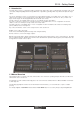
SD10 - Getting Started 1.1 Introduction The Digico SD10 consists of a worksurface with an onboard audio engine and a range of onboard inputs and outputs. This can be connected to multiple Input/Output Rack Units by MADI links or optical fibre (optionally) which carry all the audio input and output signals.
SD10 - Getting Started 1.3 Before You Start There are certain general operating principles and terms that should be understood before continuing to use this manual. Please read this chapter carefully before proceeding. 1.3.1 Worksurface Layout..............................................................
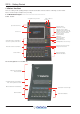
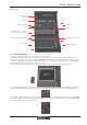
SD10 - Getting Started Right Section Space for Keyboard & Trackball Smart Keys Snapshot Automation Macros Monitoring Talkback Assignable Rotaries and Switches Aux / Pan / Dynamics Controls Mute and Channel Select Buttons Channel Faders Right Section Screen Assign Bank Select Buttons 1.3.2 Screen Assignment ............................................................... The SD10 touchscreen is used to access many of the console's functions.
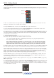
SD10 - Getting Started 1.3.3 Layers and Banks ................................................................. The SD10's worksurface is divided into Layers and Banks. Each Bank contains twelve channels, and the channels which are currently active on the control surface are defined using the fader bank and bank layer buttons to the right of the Channel Strip section’s faders: Select a Layer Select a Bank A ‘bank’ is a set of twelve faders, and a ‘layer’ contains up to four ‘banks’.
SD10 - Getting Started 1.3.5 The Assigned Channel ......................................................... One of the channels in the Channel Strip panel is displayed in gold, indicating that it is currently the Assigned Channel. This means that it has been assigned to the worksurface controls and can be configured in detail, as described below. To Assign a channel, touch anywhere in the channel on the screen (except the Aux Send area).
SD10 - Getting Started 1.3.7 Other Centre Section Controls .............................................
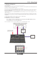
SD10 - Getting Started 1.4 Hardware Configuration 1.4.1 Connections .......................................................................... Detailed information on the various systems of connection is provided in the relevant Appendix but the following diagram provides an overview of a single console/single rack setup. All connections should be made before switching on the console and racks. The console and rack each have dual redundant power supplies and both should be switched on at all times.
SD10 - Getting Started 1.4.2 Audio I/O Panel..................................................................... The Audio I/O window is used to configure the physical I/O connected to the SD10, including configuring and naming the sockets of the cards installed in racks, and the setting of Pads and phantom power. Local I/O : The SD10 provides local audio I/O in the rear of the console. These operate independently of connected racks.
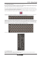
SD10 - Getting Started 1.4.3 Opto V220 (DiGiRacks) and Opto V221 (SD Racks) ............. SD Series consoles can operate with either one of two different Optocore firmware versions - V220 and V221. V220 is compatible with DiGiRacks and MiNiRacks and cannot be used with SD Racks or DRacks. V221 is compatible with SD Racks, SD MiNiRacks, NaNoRacks and DRacks, and cannot be used with DiGiRacks and MiNiRacks.
SD10 - Getting Started Manual Conforming of Rack: Select each card (column) and manually select the appropriate card in the Card/Slot Type drop down menu in the lower section of the window (displayed when the Cards & Sockets button towards the bottom-left is selected). Once the correct card type is selected, the Label at the bottom the selected card will turn green, indicating the card type matches the card installed in the rack.
SD10 - Getting Started 1.5 Configuring a Session The SD10 has a default setup which means that the new user need not get involved in configuring the desk at this stage. However, here is a brief overview of how the different displays are used in putting together a session. Each of the master displays introduced below are described fully within the rest of the manual.
SD10 - Getting Started Clear All Buttons: When changing routing, you have the option of clearing any non-default routing or processing (EQ, dynamics etc) from the channels in the session. This is especially useful when restructuring an existing session to make a new session. The clear snapshots, clear automation and clear macro’s perform similar operations. Rebuild Banks: When changing the session structure, there are two possible scenarios.
SD10 - Getting Started 1.6 Saving and Loading Sessions 1.6.1 Save As New File ................................................................. When you change the configuration of the a session you should save under a new filename. If the Save Session panel has not appeared automatically after a session restructure then touch the Files button on the Master screen and then press Save As New File.
SD10 - Getting Started 1.7 Audio Sync The SD10 will operate at Sample Rates of either 48000Hz (48kHz) or 96000Hz (96kHz). By default, it is set to clock internally (as a Master) at 48kHz. To switch the clock to 96kHz, open the Session Structure dialogue in the File menu and click on the appropriate sample rate button at the top of the window. Within a normal setup, the SD10 will usually remain as clock master. However, there are times when the SD10 needs to be clocked externally.
SD10 - Getting Started 1.8 Routing Basics 1.8.1 Selecting Inputs & Outputs ................................................... All channel input, output, insert send and insert return routing is done via routing displays, accessed via the dark grey routing buttons in the channel Setup and Output displays (shown below for an Input channel’s input).
SD10 - Getting Started For input and insert return routing, the INTERNAL port provides the following signal groups: Misc: The oscillator, white and pink noise generators. Graphic EQs: The outputs of the SD10’s internal graphic EQ’s. Effects: The outputs of any effects sends that have been created Channels: The direct outputs from the other input channels Groups: The outputs of the group busses Auxes: The outputs of the auxiliary busses.
SD10 - Getting Started For Input channels, note that if the channel input signal is changed once a channel has been manually named, the channel name will no longer follow the input signal name. To reactivate the automatic channel naming function, clear the name and re-select the channel input. Note also that the channel Output display also provides access to this channel naming facility. Channels can also be named directly in the Channel List display (in the Layout menu).
SD10 - Getting Started 1.9.2 Dynamics .............................................................................. The dynamics are accessed by touching the words Comp or Gate just below the EQ graph on screen to open the dynamics panel. There are two dynamics modules, the first of which can function as a simple compressor, a 3 way multiband compressor, or a de-esser, according to the comp/multi/desser button to its left.
SD10 - Getting Started 1.9.3 Auxiliaries ............................................................................. The auxiliaries can be accessed by touching the auxiliary row on screen or using the Screen Scroll buttons on the left of the worksurface Using either of these methods, the highlighted auxiliaries on the input screen will change.
SD10 - Getting Started 1.10 The Matrix To open the Matrix Inputs panel, touch the Matrix button on the Master Screen Menu. The window that opens allows you to route inputs to the Matrix Output Channels, and set the Matrix crosspoint levels. To route an input, touch the top of the appropriate Matrix column. This opens a standard SD10 input routing page.
SD10 - Getting Started 1.11 Control Groups Any number of input channels and output channels can be connected to one or more of the 24 Control Groups. They can then all be operated from a single worksurface channel. Changes to the Control Group fader, mute or solo or controls will affect all channels connected to the group.
SD10 - Getting Started 1.12 Solo Setup The SD10 Solo panel is accessed from a button at the top of the Master Screen. Some of the controls on this panel are duplicated on the right worksurface section. There are two solo busses and each channel on the console can be independently assigned to use Solo1, Solo2 or Solo 1+2. Therefore, if the console was being used for Stage monitors, the first solo buss could feed “In-Ear” monitors, and the second solo buss could feed a wedge.