
User guide


SD10 - Getting Started
1-7
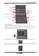
1.4 Hardware Configuration
1.4.1 Connections ..........................................................................
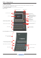
Detailed information on the various systems of connection is provided in the relevant Appendix but the following diagram provides
an overview of a single console/single rack setup.
All connections should be made before switching on the console and racks.
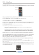
The console and rack each have dual redundant power supplies and both should be switched on at all times. After switching on
the console the software will be launched automatically and the state of the worksurface and settings should be the same as
when it was last Shut Down.
To Shut Down the console press the System>Shut Down button and wait until you receive a message saying that it is safe to
switch the power off.
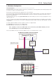
The SD10 worksurface has 8 analogue I/O and 8 AES I/O on its rear panel and remote I/O racks are available in several formats.
These racks can be connected to the console with 2x 100M high specification 75Ohm coaxial cables fitted with BNC connectors,
or optical fibre.
In normal operation the MADI connections should be as follows (see diagram below):
Rack MAIN MADI IN connected to the console MADI 1A OUT
Rack MAIN MADI OUT connected to the console MADI 1A IN
Note - Optionally, a second set of MADI cables can be connected to provide MADI redundancy from the
rack's AUX MADI ports to the console's MADI 1B ports
The console's MADI Port 2 can be connected to a MADI recorder or a second DiGiCo Rack or console.
Optional Remote Control
Laptop connection with
E
thernet Crossover Cable
STANDARD CONNECTION WITH MADI
MAIN MADI
IN
MAIN MADI
OUT
MADI 1A OUT
MADI 1A
MADI INPUTS
MADI OUTPUTS
MADI 1BMADI 2AMADI 2B
MADI IN
MADI 1A IN
MADI OUT
Remote I/O Rack
AUX MADI
IN
AUX MADI
OUT
MADI 1B OUT
MADI 1B IN
Optional
Redundant
MADI
Connection
SD10 Rear Panel MADI Connections
MADI 2A IN
MADI 2B OUT
Optional
MADI Recorde
r
or
Second I/O Rac
k