
User guide


SD10 - Getting Started
1-6
1.3.7 Other Centre Section Controls.............................................
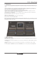
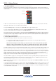
To the left of the Channel Strip panel are more channel controls: When pressed, the 2nd function button allows access to
different parameters:
1) Stereo Aux Pan and Pre/Post switching
2) Hard Mute of a channel
3) Fine adjustment of Delay settings on output channels
The Option/All button has 2 main functions:
1) When pressed and released, any channel that is a member of a gang will be temporarily isolated from that gang.
2) When pressed and held, any parameter that is adjusted on a single channel will also be adjusted in the same way
on all of the channels in that bank
1.3.8 Channel Types ......................................................................
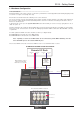
The signal flow of the SD10 is best understood in terms of the four channel types contained within it, shown below. Each channel
type offers full signal processing capabilities. As a summary, the four channel types are as follows:
- Input channels bring signals into the console to be mixed and sent to aux and group busses.
- Aux channels send a variety of mixes of the Input channels to the Aux outputs, mainly for use as monitor mixes and FX
sends.
- Group channels mix groups of input channels together, to feed the buss outputs or the output matrix.
- Matrix channels send the outputs of the matrix to the console’s main outputs (Optionally).
The Group channels, Aux channels and Matrix channels are all referred to as output channels. While the Aux and Matrix channels
are the channel types most commonly routed to outputs, all four channel types can be routed directly to outputs.
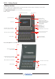
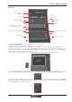
Input Module - Touch to Expand
Analogue Gain/Digital Trim
Phase - Gain Tracking
Main/Alt Input Select
Inputs
Insert A Routing & On/Off
HPF/LPF
4 Band Dynamic EQ
Touch To Expand
Multiband Dynamics
Touch To Expand
Insert B Routing & On/Off
Aux Sends
Touch to Assign Rows
Channel Pan
Mute Indicators
Channel Label
R
outing Module - Touch to Expand
Gang & Safe Indicators
Groups
Auxes
Matrix
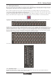
Channels are laid out in banks of 12 on the console worksurface and can be identified by their colour: Light-blue for Input chan-
nels, red for Group channels, purple for Aux channels and blue-green for Matrix channels.
By default, the Input Channels will be assigned to Layer 1 on the left and right sections of the console. Output channels (Groups,
Auxes and Matrices) and Control Groups will be assigned to the centre section. These bank assignments can be customised by
the user and saved in a session at any time.
Holding any bank or layer button down for a couple of seconds will switch all 3 worksurface sections to the same bank level or
layer.
The controls on each different type of output channel are similar but an input channel has a number of additional features.