SD11 Operation Manual User Manual - Getting Started To be read in conjunction with the SD Series Software Reference User Manual Version B for Software Versions 4.0.
SD11 Operation Manual 0-2
SD11 Operation Manual 0-3
SD11 Operation Manual Copyright © 2014 Digico UK Ltd All rights reserved. No part of this publication may be reproduced, transmitted, transcribed, stored in a retrieval system, or translated into any language in any form by any means without the written permission of Digico UK Ltd. Information in this manual is subject to change without notice, and does not represent a commitment on the part of the vendor.
SD11 Operation Manual Contents 1.1 Introduction .............................................................................. .......1-1 1.2 Manual Overview ..................................................................... .......1-1 1.3 Before You Start ....................................................................... .......1-2 1.3.1 Worksurface Layout ...................................................... .......1-2 1.3.2 Screen Assignment .....................................................
SD11 - Getting Started 1.1 Introduction The Digico SD11 consists of a rack-mountable worksurface with an onboard audio engine and a range of onboard inputs and outputs. This can be connected to multiple Input/Output Rack Units by CAT5 cable or MADI links which carry all the audio input and output signals.
SD11 - Getting Started 1.3 Before You Start There are certain general operating principles and terms that should be understood before continuing to use this manual. Please read this chapter carefully before proceeding. 1.3.1 Worksurface Layout..............................................................
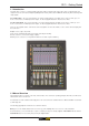
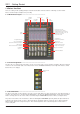
SD11 - Getting Started 1.3.4 Using the Control Surface .................................................... There are two main ways in which all of the functions of the SD11 are accessed: 1. The touchscreen display, which can be controlled directly using a finger, or by using the keyboard and mouse 2. The physical encoders, switches and faders. Note that when touching the screen directly, you may find it easier to use a finer point than your finger.
SD11 - Getting Started Six aux sends can be displayed in the Channel Strip panel at any one time. If more than six aux sends have been created in the session, the scroll button outside the bottom left-hand corner of the screen can be used to scroll the display through the remaining auxiliaries. The controls to the right of the Channel Strip panel allow the Assigned channel to be adjusted: 1.3.6 The Master Fader ..................................................................
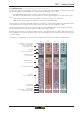
SD11 - Getting Started 1.3.8 Channel Types ...................................................................... The signal flow of the SD11 is best understood in terms of the four channel types contained within it, shown below. Each channel type offers full signal processing capabilities. As a summary, the four channel types are as follows: sends. - Input channels bring signals into the console to be mixed and sent to aux and group busses.
SD11 - Getting Started 1.4 Hardware Configuration 1.4.1 Connections .......................................................................... Detailed information on the various systems of connection is provided in the relevant Appendix but the following diagram provides an overview of a single console/ rack setup. The racks may have dual redundant power supplies and both should be switched on at all times.
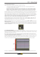
SD11 - Getting Started Most of the right-hand section of the panel consists of a graphical representation of the rack configuration connected to the selected port. Depending on the port selected, the graphic will change, showing the available physical I/O. Each small “square” on the image represents a single physical audio connection or socket, with these arranged in columns or rows, representing I/O cards in racks, or the local I/O on the back of the console.
SD11 - Getting Started Select the port to be configured Edit the Port Name here. Eg. Stage Rack, Local Rack etc... Copy Rack Audio to MADI Auto Conforming for all ports, individual racks, or individual cards Select the contents of the bottom-right corner of the Audio IO window Select Card Type manually or using Auto-Conform function, and edit Group Name Selected Socket Properties Edit Name and Socket options.
SD11 - Getting Started 1.5 Configuring a Session The SD11 has a default setup which means that the new user need not get involved in configuring the desk at this stage. However, here is a brief overview of how the different displays are used in putting together a session.
SD11 - Getting Started Clear All Buttons : When changing routing, you have the option of clearing any non-default routing or processing (EQ, dynamics etc) from the channels in the session. This is especially useful when restructuring an existing session to make a new session. The clear snapshots, clear automation and clear macro’s perform similar operations. Rebuild Banks : When changing the session structure, there are two possible scenarios.
SD11 - Getting Started 1.6 Saving and Loading Sessions 1.6.1 Save As New File ................................................................. When you change the configuration of the a session you should save it to the console's flash drive under a new filename. If the Save Session panel has not appeared automatically after a session restructure then touch the Files button on the Master screen and then press Save As New File.
SD11 - Getting Started 1.7 Audio Sync The SD11 operates a Sample Rates of either 48000Hz (48kHz) or 96000Hz (96KHz). By default, it is set to clock internally (as a Master). The Audio Synchronisation panel allows you to set the console to be clocked externally. To open the Audio Synchronisation Panel, touch the Setup Menu button, followed by Audio Sync: The SD11 will clock from the back panel Word Clock connection, or from equipment connected via CAT 5 or MADI.
SD11 - Getting Started 1.8 Routing Basics 1.8.1 Selecting Inputs & Outputs ................................................... All channel input, output, insert send and insert return routing is done via routing displays, accessed via the dark grey routing buttons in the channel Setup and Output displays (shown below for an Input channel’s input). To access Channel Input Setup, touch the top of an input channel display on the touchscreen.
SD11 - Getting Started Note: The outputs for the channel being routed are locked out of the signal list. Note also that the console views all routes as a single list. Therefore, if the left signal is connected to the last signal in a port, the right signal, will be automatically connected to the first signal of the next port, regardless of port type.
SD11 - Getting Started 1.9 Channel Processing 1.9.1 EQ .......................................................................................... The EQ section comprises four user-configurable parametric filters and a pair of swept High-pass and Low-pass filters. The EQ is accessed by touching the on screen display to Assign the channel (the colour changes to yellow) and then using the controls on the right hand side of the screen.
SD11 - Getting Started 1.9.2 Dynamics ............................................................................... The dynamics are accessed by touching the words Comp or Gate just below the EQ graph on screen to open the dynamics panel. The worksurface controls beneath the screen control the various parameters. Touching the Close button in the top right corner of the panel will close it. Dedicated Threshold, Gain controls and In/Out switches can be found on the right hand side of the screen.
SD11 - Getting Started 1.9.3 Auxiliaries ............................................................................. The auxiliaries can be accessed by touching the Aux Quick Select button, the auxiliary row on screen or using the Screen Scroll buttons. Using either of these methods, the highlighted auxiliaries on the input screen will change.
SD11 - Getting Started 1.10 The Matrix To open the Matrix Inputs panel, touch the Matrix button on the Master Screen Menu. The window that opens allows you to route inputs to the Matrix Output Channels, and set the Matrix crosspoint levels. To route an input, touch the top of the appropriate Matrix column. This opens a standard SD11 input routing page.
SD11 - Getting Started 1.11 Control Groups Any number of input channels and output channels can be connected to one or more of the 8 Control Groups. They can then all be operated from a single worksurface channel. Changes to the Control Group fader, mute or solo or controls will affect all channels connected to the group.
SD11 - Getting Started 1.12 Solo Setup The SD11 Solo panel is accessed from a button at the top of the Master Screen. Some of the controls on this panel are duplicated in the solo panel above the touchscreen. There are two solo busses and each channel on the consoles can be independently assigned to use Solo1, Solo2 or Solo 1+2. Therefore, if the console was being used for Stage monitors, the first solo buss could feed “In-Ear” monitors, and the second solo buss could feed a wedge.