
Owner's manual


SD7 - Getting Started
1-4
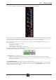
To the right of the Master Panel is a single encoder marked Touch-Turn (shown below). This is used to access any rotary
controls within the Master Panel. To assign the Touch-Turn encoder to a particular on-screen pot, touch the pot to be assigned.
You will notice that a coloured ring appears around the on-screen pot, indicating that it is assigned to the Touch-Turn encoder.
The colour of this ring is unique to that control, and is also reflected in the base of the Touch-Turn encoder, providing further
indication of which pot is currently assigned to it.
1.3.4 The Assigned Channel .........................................................
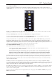
One of the channels in the Channel Strip panel is displayed in gold, indicating that it is currently the Assigned Channel. This means
that it has been assigned to the worksurface controls and can be configured in detail, as described below. To Assign a channel,
touch anywhere in the channel on the screen except the Aux Send area of the input channels. Alternatively, use the ch left and
right buttons at the bottom of the channel worksurface controls to scroll through the channels in the panel:
Note that these left and right arrows are duplicated in the channel Setup and Output displays.
Note also that the Channel List display provides another method for assigning a channel to the worksurface
controls.
Once a channel is Assigned, all of the controls for that channel which are not displayed within the channel strip itself can be
accessed via secondary pop-ups, displayed by touching inside the relevant area of the channel. These pop-ups include controls
such as input and output routing and signal processing parameters.
A number of the physical rotary encoders on the control surface can be assigned to different on-screen pots. In order to ensure
that it is clear which function is assigned to which encoder, the assigned on-screen pot will have a coloured ring around it which
will be reflected in the colour of the light around the base of the encoder on the control surface.
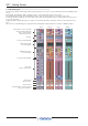
The twelve encoders and buttons immediately above the Channel Strip panel (shown above) refer to the channels with which
they are aligned. These controls are concerned with the channel input, located at the top of the Channel Strip panel.
The three rows of encoders and buttons immediately below the Channel Strip also refer to the channels with which they are
aligned. Normally, these control the level and on/off status of the three highlighted aux sends, but can have a number of functions
assigned to them. Touching on an aux send on the screen will assign that aux and the ones immediately below it to the aux
encoders. Six aux sends can be displayed in the Channel Strip panel at any one time. If more than six aux sends have been
created in the session, the scroll button outside the bottom left-hand corner of the screen can be used to scroll the display
through the remaining auxiliaries: