D i g i g r a m ES881 ES1241 ES16161 USER’S MANUAL M ANUEL U TILISATEUR Networking Your Sound
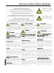
EtherSound ES881, ES1241 & ES16161 Ethernet Audio Bridges Important Safety Information read carefully before using this equipment! Follow these instructions and keep them in a safe place! Keep in mind that damages due to failure to observe the instructions contained in this manual are not covered by warranty. Instructions importantes de sécurité lire soigneusement avant d'utiliser l'équipement! Lisez et suivez ces instructions.
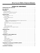
EtherSound ES881, ES1241 & ES16161 Ethernet Audio Bridges TABLE OF CONTENTS INFORMATION FOR THE USER ........................................................................................................................................ 3 KEY FEATURES ................................................................................................................................................................................... 4 OVERVIEW ...................................................................
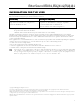
EtherSound ES881, ES1241 & ES16161 Ethernet Audio Bridges INFORMATION FOR THE USER This equipment has been tested and found to comply with the limits for a CLASS B digital device, pursuant to Part 15 of the FCC Rules and with the following European and international Standards for: Electrical safety: Electromagnetic Compatibility: Europe : EN60950, 3rd edition European Directive 73/23/CEE “Low Voltage Directive“ International: IEC 60950, 3rd edition Europe: EN55022:1998 + A1:2000, Class B / EN55024 : 1998
D i g i g r a m You have just acquired a Digigram EtherSound audio bridge and we congratulate you! Digigram EtherSound ES881 / ES1241 / ES16161 are equipped with AES/EBU interfaces including hardware sample rate converters (SRC). They allow the realization of flexible and powerful EtherSound networks. The manual at hand will guide through installation and operation. For any software related issue, please refer to the specific documentation provided in its on-line help.
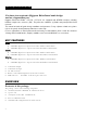
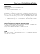
EtherSound ES881, ES1241 & ES16161 Ethernet Audio Bridges The ES881, ES1241, and ES16161 front panels 1. Device status group (two orange LEDs): Primary The first LED is called “Primary”.
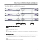
D i g i g r a m ES881, ES1241, and ES16161 back panels 1. Audio connectors On ES881, four male XLR-3 connectors are used to output eight EtherSound channels on four AES/EBU stereo outputs, four female XLR-3 connectors to input eight EtherSound channels on four AES/EBU stereo inputs. On ES1241, six male XLR-3 connectors are used to output twelve EtherSound channels on six stereo AES/EBU stereo outputs, two female XLR-3 connectors to input four EtherSound channels on two AES/EBU stereo inputs.
EtherSound ES881, ES1241 & ES16161 Ethernet Audio Bridges 3. GPIO connectors These terminal blocks allow setup of external control and monitoring devices through configurable and protected General Purpose Inputs and Outputs. See dedicated GPIO chapter for details. Note: the GPIO port is managed by configuration software only. 4. Serial port RS232 interface on DB9. Note: The RS232 serial port management requires specific software. 5.
D i g i g r a m INSTALLATION Before mounting devices in a rack… Internal settings On ES881, ES1241, and ES16161 the local sampling frequency is switchable by means of a jumper between 44.1 kHz and 48 kHz. Preset default value is 48 kHz. In case you need to change the default setting, please refer to appendix B of this manual. Note: These operations require opening of the cabinet and shall be done by qualified personnel only.
EtherSound ES881, ES1241 & ES16161 Ethernet Audio Bridges Synchronization ES881, ES1241, and ES16161 support several synchronization modes. Synchronization via: • the network (except in ‘Primary Master’ mode) • the ‘AES In 1’ input • the Word clock input If the equipment is ` Primary Master', it provides the clock for the network It can be synchronized on the internal clock or on the signal connected to the “AES In 1”, or on the signal connected to the Word Clock input.
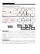
D i g i g r a m Serial port (RS232 on DB9) Pin # Description 1 not connected 2 RxD (received data) 3 TxD (transmitted data) 4 not connected 5 signal ground 6 not connected 7 RTS (request to send) 8 CTS (clear to send) 9 not connected ES881, ES1241, and ES16161 dispose of a serial ES16161 RS232 male port on the rear panel. Use this port to connect any compatible device. For pinout allocation details, please refer to the figure and table above.
EtherSound ES881, ES1241 & ES16161 Ethernet Audio Bridges SPECIFICATIONS Configuration Size 1U 19” rack : 43.9 x 482.6 x 297.1 mm 100 - 240 VAC, 47-63 Hz switching-mode, automatic voltage detection Power supply WARNING: Do not open the power supply module. It contains hazardous voltages. There are no user-serviceable parts inside Temp / humidity (non-condensing) Operating: Storage: 0 °C - 50 °C / 0% - 95% -5 °C – 70 °C / 0% - 95% Power consumption ES881/ES1241/ES16161 : 0.23 A at 100 V, 0.
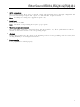
D i g i g r a m APPENDIX A: GPIO CONNECTORS ES881, ES1241, and ES16161 feature four optocoupled GPIs and four relay GPOs. GPIs allow sending commands to the EtherSound configuration software, GPOs can be used by the EtherSound configuration software for remote control of external devices. The GPIO pins are labeled 1 through 8 on the rear panel as illustrated. General Purpose Inputs (GPIs) Schematic diagrams show the particular design for each GPI. The GPI status can be either “1” or “0”.
EtherSound ES881, ES1241 & ES16161 Ethernet Audio Bridges GPI optocoupler specifications minimum current i min to switch GPI 0,5 mA Maximum current i max supported 50 mA i calculation rule (GPi #3 & #4) i (mA) = Vin - 1,2 3,3 Maximum voltage V in supported 50 Vdc Maximum reverse voltage V in supported 6V General Purpose Outputs (GPOs) The ES8 GPOs are relay outputs. They feature two pins each and are all configured the same way.
D i g i g r a m APPENDIX B: SETTING THE INTERNAL JUMPER These settings shall be executed by qualified personnel only! Tools required: • • • a #1 Pozidriv screwdriver an ESD-preventive wrist strap a small flat blade screwdriver Electrostatic discharge (ESD) can damage several components on the board. To avoid such damage in handling the board, take the following precautions: Bring the device and everything that contacts it to ground potential by providing a conductive surface and discharge paths.
EtherSound ES881, ES1241 & ES16161 Ethernet Audio Bridges Selct sampling frequency This jumper allows for modification of theES881, ES1241, and ES16161 sampling frequency. The default value is preset to 48 kHz. It can be set to 44.1 kHz. Note that this setting is effective only if the ES881 is the Primary Master of the EtherSound network, as the Primary Master is the device providing the clock for the entire network.
D i g i g r a m APPENDIX C: GLOSSARY AUDIO CHANNEL An audio channel is a single mono audio signal. By extension, an audio channel is one of the 64 slots of an EtherSound frame, i.e. a signal sampled at 48 KHz with a 24-bit resolution. SWITCH Device to connect two segments of a Local Area Network.
EtherSound ES881, ES1241 & ES16161 Ethernet Audio Bridges SLAVE An EtherSound device that receives the EtherSound stream and restores standard audio is called a Slave. A Slave answers to the status requests and commands of the Primary Master. STAR Star is a network topology where all devices are connected to a same unit (a switch in the following picture) that is handling all the communications.
Digigram (www.digigram.com) digital audio solutions are key to the success of public address and pro sound installations, as well as broadcast and media production companies worldwide.We develop innovative networked audio devices, computer sound cards, and audio management software. Digigram Powered solutions are installed in thousands of radio and television stations; corporate and commercial sound installations; and audio recording and video post-production facilities around the globe.