
User's Manual

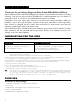


Table Of Contents
- AUDIO CHANNEL
- DAISY CHAIN
- dBV, dBu
- Two different units expressing the voltage level using logar
- FRAME
- GPIO
- MASTER
- PRIMARY MASTER
- SLAVE
- STAR
- SWITCH
- CANAL AUDIO (AUDIO CHANNEL)
- COMMUTATEUR (SWITCH)
- DAISY CHAIN (branchement en série)
- dBV, dBu
- Deux unités différentes exprimant un niveau de tension en ut
- GPIO (entrées/sorties Tout Ou Rien)
- MASTER
- PRIMARY MASTER
- SLAVE
- SSI
- STAR (étoile)

EtherSound ES8in, ES8mic & ES8out
Ethernet Audio Bridges
Connect a standard Ethernet cable between an ES8in/ES8mic “OUT” (“TO”) port to the “IN” (“FROM”) port of
an ES8out device. Select the ES8in/ES8mic and ES8out channels accordingly (see “Setting the EtherSound
channels” chapter).
Example 2: adding more devices
You can easily insert further ES8 devices to build a simple daisy chain. There are only two rules to follow:
1. The first device in the chain is necessarily the Primary Master, typically an ES8in/ES8mic.
2. Install the devices in the chain starting from the Primary Master; connect its “OUT” (“TO”) port to the
“IN” (“FROM”) port of the next device, connect its “OUT” (“TO”) port to the “IN” (“FROM”) port of
the following device, and so on.
Example 3: more complex architectures
System topology may be daisy chain, star, or a combination of both. The first device in a network, such as an
EtherSound ES8in/ES8mic, provides the master clock for the entire network.
Connect the one device's “OUT” (“TO”) port to the “IN” (“FROM”) port of the following device (EtherSound
ES8in/ES8mic for inserting additional channels or EtherSound ES8out for extracting existing channels).
Repeat this step for each device in the network. The maximum distance between two devices is 100 meters
(328 feet). Intermediate switches or fiber optic links may be used to considerably increase this distance.
All EtherSound devices “downstream” from an audio source can play the corresponding network channel.
Connecting a computer to manage the EtherSound network
To connect a PC directly to ES8in/ES8mic, it must be equipped with a network card. Use a
crossover Ethernet cable
to connect the network card to the “IN” (“FROM”) port of the
Primary Master.
You can also access the Primary Master through a conventional Ethernet network; in this case, use a standard
Ethernet cable (e. g. connected to a switch)
Audio
Depending on the ES8 model purchased, balanced inputs and outputs are available either on eight XLRs or on
a terminal block on the rear panel. The pinout used on the XLRs is standard: pin 1 carries the signal ground,
pin 2 carries the positive signal (“hot”, +) and pin 3 carries the negative signal (“cold”, -).
The pinout of the terminal block is depicted beneath the strip:
These balanced connections are
compatible with unbalanced audio
sources and destinations: just wire
both cold pin and ground pin on ES8
to the ground of the unbalanced signal,
and the ES8 hot pin to the signal.
By default, ES8in/ES8mic nominal input level is set to +4 dBu; for details, see Appendix B.
By default, ES8out nominal output level is +4 dBu. The value can be adjusted for each channel through
management software and stored in the ES8out device.
GPIO
ES8in/ES8mic and ES8out are shipped with four GPIs and four GPOs on terminal blocks, counterparts are
supplied. For details see Appendix A.
9