D i g i g r a m PCX1221e PCX1222e Professional Multichannel Sound Cards User’s manual
D i g i g r a m For technical support, please contact your system supplier Digigram S.A. Parc de Pré Milliet, 38330 Montbonnot - FRANCE Tel: +33 (0)4 76 52 55 01• Fax: +33 (0) 4 76 52 53 07• E-mail: info@digigram.com Digigram Inc. 2101 Wilson Boulevard, Suite 1004, Arlington, VA 22201-USA Tel: +1 703 875 9100 • Fax: +1 703 875 9161 • E-mail: input@digigram.com Digigram Asia Pte Ltd.
PCX1221e & PCX1222e User’s Manual Table of Contents INFORMATION FOR THE USER ............................................................................... 4 IMPORTANT NOTICE ......................................................................................................... 4 CONTENTS OF THIS PACKAGE ............................................................................... 5 FEATURES ...............................................................................................................
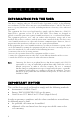
D i g i g r a m INFORMATION FOR THE USER This device complies with part 15 of FCC rules. Operation is subject to the following two conditions: (1) This device may not cause harmful interference, and (2) This device must accept any interference received, including interference that may cause undesired operation. This equipment has been tested and found to comply with the limits for a CLASS B digital device, pursuant to Part 15 of the FCC Rules.
PCX1221e & PCX1222e User’s Manual Warning: Electrostatic discharge (ESD) can damage several components on the board. To avoid such damage in handling the board, take the following precautions: Bring the device and everything that contacts it to ground potential by providing a conductive surface and discharge paths. As a minimum, observe these precautions: • • • • Disconnect all power and signal sources. Place the device on a grounded conductive work surface.
D i g i g r a m FEATURES PCX1222e and PCX1221e are audio cards for PCI EXPRESSTM (PCIe®). They are in PCI EXPRESSTM x1 format and can thus be plugged into any PCIe® slot (x1, x2, x4, x8, x16, x32).
PCX1221e & PCX1222e User’s Manual Main software features • • • Real-time, simultaneous record and playback in PCM (8, 16 and 24 bits) as well as in MPEG Audio Layer I, Layer II and Layer IIIL, Float IEEE754 conversion supported (with 24-bit fixed-point dynamic range) When using the np SDK, real-time mixing of several PCM and MPEG audio streams, direct monitoring, level adjustment, panning, cross-fades, punch-in/punch-out, scrubbing, time-stretching, pitch-shifting, 3-band parametric equalizer, maximizer,
D i g i g r a m PCX1221e and PCX1222e cards run under Windows 2000, XP∗, and Windows Server 2003 ∗ . HARDWARE INSTALLATION The card has to be installed in the computer prior to installing its driver. Installing the card Gently plug the card into a free PCI slot and press it down to position it firmly. Tighten the screw. Interrupt and memory address Hardware interrupt and addresses are automatically set up at start-up by the PCI PnP BIOS.
PCX1221e & PCX1222e User’s Manual Please note that, with the DHS installed, controls available through the DirectSound control panel are limited to: • Volume control for input and output • Wave control You may also install the driver without installing the DHS control panel, and in this case more controls available are through the DirectSound control panel: • Volume control for input • Wave control • Monitoring control • Analog input level • Digital input level • Clock selection: AES Sync, AES1, Word Clock
D i g i g r a m Parameterizing the ASIO driver • To use the ASIO driver on your PCX sound card, the option “PCM only” has to be activated in the Digigram control panel (CPL). To access this control panel, go to , , , . Parameterizing the Wave driver • 10 In the case of an application managing exclusively PCM audio, the latency of the Wave driver can be optimized activating the option “PCM only” in the Digigram control panel (CPL).
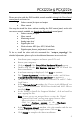
PCX1221e & PCX1222e User’s Manual Removing the driver under Windows 2000, XP, and Windows Server 2003 • • • • Open the Windows Control Panel and double-click on the Add/Remove Software icon. Select “Digigram HR Runtime …”, and Change/Remove. Select Remove in the np Runtime window. Follow the instructions to finish driver removal.
D i g i g r a m Play file to play in loop a file of your choice (PCM only). If the playback is correct, the card is correctly installed and works. • To stop the playback, right click on the card icon, and select Stop Activities. • If the card is not displayed: • Make sure that during the HR runtime installation the “Driver for the HR boards” has been selected in the “Select components” window. • Make sure that the card is correctly inserted in the PCI slot, and screwed on the PC chassis.
PCX1221e & PCX1222e User’s Manual The ‘Digigram Hardware Settings’ (‘DHS’) control panel Digigram Hardware Settings (DHS) is an application allowing to configure the hardware resources of Digigram cards for all audio applications using them. This application is installed by default with the driver unless the command line “setup x_topology” has been executed to install the driver. A resource being managed by the DHS application can not be modified by any other applications.
D i g i g r a m SPECIFICATIONS Configuration Bus/Format Digital Signal Processor RAM Size Power requirements (+3.3V / +12V) Operating: temp / humidity (non-condensing) Storage: temp / humidity (non-condensing) PCX1221e PCX1222e PCI EXPRESSTM (PCIe®) x1 (x2, x4, x8, x16, x32 compatible) Motorola 56321 at 240 MHz 512 kWords 168 mm x 111 mm x 20 mm 1.5 A / 0.1 A 3 A / 0.
PCX1221e & PCX1222e User’s Manual Outputs Analog line outputs (mono) Maximum output level / impedance Digital outputs (stereo) Programmable output gain Other outputs PCX1221e - PCX1222e 12 servo-balanced ∗∗∗ +24 dBu / <100 Ω ∗∗ 6 AES/EBU , up to 192 kHz digital: from –110 dB to +18 dB analog: from –86 dB to +24 dB digital: from –110 dB to +18 dB Word clock (up to 96 kHz) Connectors Internal connectors External connector PCX1221e PCX1222e Inter-board Sync 68-pin SCSI MDR Audio specifications PCX1221
D i g i g r a m Audio Performance measured at Fs=48 kHz PCX1221e PCX1222e - 20 Hz–20 kHz: ±0.3 dB - <0.
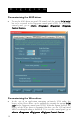
PCX1221e & PCX1222e User’s Manual APPENDICES PCX1221e Schematic Diagram CRYSTAL Word Clock Video AES/EBU Sync RECEIVE CLOCK GENERATION AES/EBU IN 1 DSP RECEIVE TRANSMIT SRC AES/EBU OUT 1 - 6 Bypass LTC INTERFACE PCIe BUS PCX1222e Schematic Diagram CRYSTAL Video Word Clock RECEIVE AES/EBU Sync CLOCK GENERATION AES/EBU IN 1 RECEIVE SRC Bypass ANALOG LINE IN 1 – 2 TRANSMIT AES/EBU OUT 1 - 6 DAC LINE OUT 1 - 12 DSP ADC Level adjust LTC INTERFACE PCIe BUS 17
D i g i g r a m Cable diagram Schematic diagram of the cable delivered by Digigram*: 3 3 3 3 3 3 3 3 1 3 3 3 3 J1 3 3 2 J4 OUT 10 J5 OUT 11 J6 OUT 12 J7 OUT 1 J8 OUT 2 J9 OUT 3 J10 OUT 4 J11 OUT 5 J12 OUT 6 J13 OUT 7 J14 OUT 8 J15 3 3 3 XLR-3P Male 2 3 1 J16 J17 AES EBU OUT 1 J19 AES EBU OUT 2 J20 AES EBU OUT 3 J21 AES EBU OUT 4 J22 WORD CLOCK IN J23 WORD CLOCK OUT J24 AES EBU SYNC J25 VIDEO IN J26 LTC IN J27 * Your cable may look different if it
PCX1221e & PCX1222e User’s Manual Wiring diagram J1 62 61 21 20 41 40 + 38 37 + 35 34 + 32 31 58 57 17 16 + 56 55 15 14 + 54 53 + 13 12 + 52 51 + 11 10 + 44 43 26 25 + 29 28 + 48 47 + 8 7 + 46 45 6 5 49 + + + + + S h ell S h ell S h ell S h ell S h ell S h ell S h ell S h ell S h ell S h ell S h ell S h ell S h ell S h ell + S h ell S h ell S h ell S h ell + + + S h ell S h ell S h ell C e nter 2 3 1 2 3 1 2 3 1 2 3 1 2 3 1 2 3 1 2 3 1 2 3 1 2 3 1 2 3 1 2 3 1 2 3 1 2 3 1
g r Digital Pin 1 2 3 4 5 6 7 8 9 10 Signal AES/EBU IN 6 + AES/EBU IN 6 AES/EBU SYNC + AES/EBU SYNC NC NC GND GND AES/EBU OUT 4 + AES/EBU OUT 4 - Pin 11 12 15 16 35 36 37 38 39 40 Signal Pin Signal AES/EBU OUT 2 + 41 GND AES/EBU OUT 2 - 42 GND Video IN 43 AES/EBU OUT 3 + GND 44 AES/EBU OUT 3 AES/EBU IN 5 + 45 AES/EBU OUT 1 + AES/EBU IN 5 46 AES/EBU OUT 1 Reserved 47 Word Clock IN Reserved 48 GND AES/EBU IN 1 + 49 Word Clock OUT AES/EBU IN 1 50 GND Analog D i g i a m Pin 13 14 17 18 19 20 21 22