
Datasheet

Basys 3™ FPGA Board Reference Manual
Copyright Digilent, Inc. All rights reserved.
Other product and company names mentioned may be trademarks of their respective owners.
Page 10 of 19
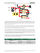
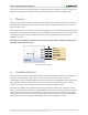
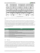
The mouse assumes a relative coordinate system wherein moving the mouse to the right generates a positive
number in the X field, and moving to the left generates a negative number. Likewise, moving the mouse up
generates a positive number in the Y field, and moving down represents a negative number (the XS and YS bits in
the status byte are the sign bits – a '1' indicates a negative number). The magnitude of the X and Y numbers
represent the rate of mouse movement; the larger the number, the faster the mouse is moving (the XV and YV
bits in the status byte are movement overflow indicators – a '1' means overflow has occurred). If the mouse moves
continuously, the 33-bit transmissions are repeated every 50ms or so. The L and R fields in the status byte indicate
Left and Right button presses (a '1' indicates that the button is being pressed).
L R 0 1 XS YS XY YY P X0 X1 X2 X3 X4 X5 X6 X7 P Y0 Y1 Y2 Y3 Y4 Y5 Y6 Y7 P1 0 1 00 11
Idle state
Start bit
Mouse status byte X direction byte Y direction byte
Stop bit Start bit
Stop bit
Idle state
Stop bit Start bit
Figure 10. Mouse data format.
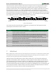
The microcontroller also supports Microsoft® IntelliMouse®-type extensions for reporting back a third axis
representing the mouse wheel, as shown in Table 4.
Table 4. Microsoft Intellimouse-type extensions, commands, and actions.
7 VGA Port
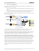
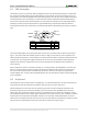
NOTE: A helpful way to understand the way that VGA signals are transmitted is to understand the method of which
CRT (Cathode Ray Tubes) function for displaying images. Although the technology may seem outdated, it is from
this legacy that many of the signal names and timings have originated.
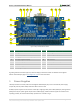
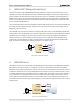
The Basys 3 board uses 14 FPGA signals to create a VGA port with 4-bits per color and the two standard sync
signals (HS – Horizontal Sync, and VS – Vertical Sync). The color signals use resistor-divider circuits that work in
conjunction with the 75 ohm termination resistance of the VGA display to create 16 signal levels each on the red,
green, and blue VGA signals. This circuit, shown in Fig. 11, produces video color signals that proceed in equal
increments between 0V (fully off) and 0.7V (fully on). Using this circuit, 4096 different colors can be displayed, one
for each unique 12-bit pattern. A video controller circuit must be created in the FPGA to drive the sync and color
signals with the correct timing in order to produce a working display system.
Command
Action
EA
Set stream mode. The mouse responds with "acknowledge" (0xFA) then resets its movement
counters and enters stream mode.
F4
Enable data reporting. The mouse responds with "acknowledge" (0xFA) then enables data
reporting and resets its movement counters. This command only affects behavior in stream
mode. Once issued, mouse movement will automatically generate a data packet.
F5
Disable data reporting. The mouse responds with "acknowledge" (0xFA) then disables data
reporting and resets its movement counters.
F3
Set mouse sample rate. The mouse responds with "acknowledge" (0xFA) then reads one more
byte from the host. This byte is then saved as the new sample rate, and a new "acknowledge"
packet is issued.
FE
Resend. FE directs mouse to re-send last packet.
FF
Reset. The mouse responds with "acknowledge" (0xFA) then enters reset mode.