
Datasheet


Basys 3™ FPGA Board Reference Manual
Copyright Digilent, Inc. All rights reserved.
Other product and company names mentioned may be trademarks of their respective owners.
Page 11 of 19
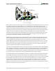
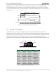
HD-DB15
4KW
2KW
1KW
100W
100W
15
10
5
11
6
1
Pin 1: Red
Pin 2: Grn
Pin 3: Blue
Pin 13: HS
Pin 14: VS
Pin 5: GND
Pin 6: Red GND
Pin 7: Grn GND
Pin 8: Blu GND
Pin 10: Sync GND
RED0
RED1
RED2
4KW
2KW
1KW
GRN0
GRN1
GRN2
RED
GRN
BLU
HS
VS
Artix-7
G19
H19
J19
P19
J17
H17
G17
R19
HSYNC
VSYNC
510W
RED3
N19
510W
GRN3
D17
4KW
2KW
1KW
BLU0
BLU1
BLU2
510W
BLU3
N18
L18
K18
J18
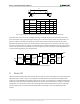
7.1 VGA System Timing
VGA signal timings are specified, published, copyrighted, and sold by the VESA® organization (www.vesa.org). The
following VGA system timing information is provided as an example of how a VGA monitor might be driven in 640
by 480 mode.
NOTE: For more precise information, or for information on other VGA frequencies, refer to documentation
available at the VESA website.
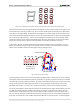
CRT-based VGA displays use amplitude-modulated moving electron beams (or cathode rays) to display information
on a phosphor-coated screen. LCD displays use an array of switches that can impose a voltage across a small
amount of liquid crystal, thereby changing light permittivity through the crystal on a pixel-by-pixel basis. Although
the following description is limited to CRT displays, LCD displays have evolved to use the same signal timings as
CRT displays (so the "signals" discussion below pertains to both CRTs and LCDs). Color CRT displays use three
electron beams (one for red, one for blue, and one for green) to energize the phosphor that coats the inner side of
the display end of a cathode ray tube (see Fig. 12).