
Datasheet


Basys 3™ FPGA Board Reference Manual
Copyright Digilent, Inc. All rights reserved.
Other product and company names mentioned may be trademarks of their respective owners.
Page 12 of 19
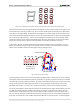
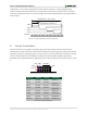
Anode (entire screen)
High voltage
supply (>20kV)
Deflection coils
Grid
Electron guns
(Red, Blue, Green)
gun
control
grid
control
deflection
control
R,G,B signals
(to guns)
Cathode ray tube
Cathode ray
VGA
cable
Figure 12. Color CRT display.
Electron beams emanate from "electron guns" which are finely-pointed heated cathodes placed in close proximity
to a positively charged annular plate called a "grid." The electrostatic force imposed by the grid pulls rays of
energized electrons from the cathodes, and those rays are fed by the current that flows into the cathodes. These
particle rays are initially accelerated towards the grid, but they soon fall under the influence of the much larger
electrostatic force that results from the entire phosphor-coated display surface of the CRT being charged to 20kV
(or more). The rays are focused to a fine beam as they pass through the center of the grids, and then they
accelerate to impact on the phosphor-coated display surface. The phosphor surface glows brightly at the impact
point, and it continues to glow for several hundred microseconds after the beam is removed. The larger the
current fed into the cathode, the brighter the phosphor will glow.
Between the grid and the display surface, the beam passes through the neck of the CRT where two coils of wire
produce orthogonal electromagnetic fields. Because cathode rays are composed of charged particles (electrons),
they can be deflected by these magnetic fields. Current waveforms are passed through the coils to produce
magnetic fields that interact with the cathode rays and cause them to transverse the display surface in a "raster"
pattern, horizontally from left to right and vertically from top to bottom, as shown in Fig. 13. As the cathode ray
moves over the surface of the display, the current sent to the electron guns can be increased or decreased to
change the brightness of the display at the cathode ray impact point.
Information is only displayed when the beam is moving in the "forward" direction (left to right and top to bottom),
and not during the time the beam is reset back to the left or top edge of the display. Much of the potential display
time is therefore lost in "blanking" periods when the beam is reset and stabilized to begin a new horizontal or
vertical display pass. The size of the beams, the frequency at which the beam can be traced across the display, and
the frequency at which the electron beam can be modulated determine the display resolution.
Modern VGA displays can accommodate different resolutions, and a VGA controller circuit dictates the resolution
by producing timing signals to control the raster patterns. The controller must produce synchronizing pulses at
3.3V (or 5V) to set the frequency at which current flows through the deflection coils, and it must ensure that video
data is applied to the electron guns at the correct time. Raster video displays define a number of "rows" that
corresponds to the number of horizontal passes the cathode makes over the display area, and a number of
"columns" that corresponds to an area on each row that is assigned to one "picture element" or pixel. Typical
displays use from 240 to 1200 rows and from 320 to 1600 columns. The overall size of a display and the number of
rows and columns determines the size of each pixel.